Torque transmission device
A technology of torque transmission device and load torque, which is applied in the direction of transmission device, gear transmission device, electromechanical device, etc. It can solve the problems of complex structure, difficulty in miniaturization, unstable switching action, etc., and achieve the effect of fewer parts
- Summary
- Abstract
- Description
- Claims
- Application Information
AI Technical Summary
Problems solved by technology
Method used
Image
Examples
Embodiment approach 1
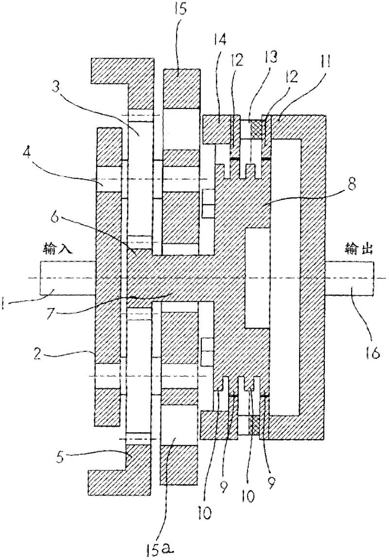
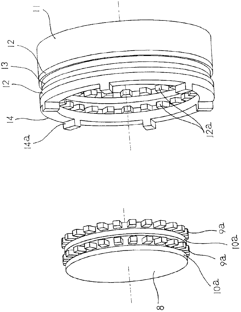
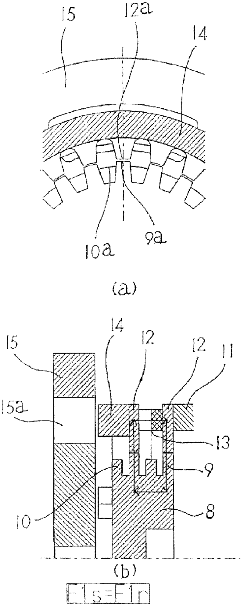
[0061] Use below Figure 1 to Figure 10 Embodiment 1 of a load sensing automatic transmission to which the torque transmission device of the present invention is applied will be described.
[0062] exist figure 1 Among them, 1 is the input shaft, 2 is the bracket fixed on the input shaft 1, 3 is the planetary gear installed on the gear shaft 4 on the bracket 2 through the shaft, and 5 is the inscribed meshing of the planetary gear 3 The internal gear 6 is a central gear arranged on the central gear shaft 7, and the planetary gear 3 is engaged externally with the central gear 6, and internally engaged with the above-mentioned internal gear 5, and the rotation of the speed-up bracket 2 makes the central gear The shaft 7 rotates at an increased speed. 8 is a low torque input mechanism linked with the sun gear shaft 7, such as figure 2 As shown, it is composed of a yoke rotating body 9 and a side magnetic body 10. The yoke rotating body 9 has a tooth-shaped portion 9a made of ...
Embodiment approach 2
[0075] Figure 11 Another aspect of the torque transmission device of the present invention is shown.
[0076] exist Figure 11 Among them, the magnetic pole rotating body 20 having the tooth-shaped portion 21 of the magnetic pole on the inner side and the yoke rotating body 22 having the tooth-shaped portion 23 on the outer side are rotatable by the rotation support mechanism as shown in the first embodiment, for example. ground support, and either side is slidably supported in the direction of the rotation centerline.
[0077] On the side of the tooth-shaped portion 23, a side magnetic body 24 is fixed, and the side magnetic body 24 is arranged at an interval in the radial direction that is wider than the interval between the tooth-shaped portion 21 and the tooth-shaped portion 23 of the magnetic pole. of the circumferential surface. exist Figure 11 In the above example, a space is provided between the tooth-shaped portion 23 and the inner peripheral portion of the side...
Embodiment approach 3
[0080] Figure 12 The present embodiment is a torque transmission device in which the yoke rotating body 22 is provided inside and the magnetic pole rotating body 20 is provided outside.
[0081] Magnetic pole rotating body 20, on the inner circumference of the hollow body, such as Figure 12 As shown, tooth-shaped portions 21a, 21b of magnetic poles periodically and alternately magnetized into N poles and S poles are formed.
[0082] The outer periphery of the yoke rotating body 22 is rotatably spaced from the inner periphery of the magnetic pole tooth-shaped portions 21a, 21b of the magnetic pole rotating body 20 so as to face the magnetic pole tooth-shaped portions 21a, 21b. The tooth-shaped portion 23 made into a tooth-shaped shape is arranged, and at its side, a side magnetic body 24 is fixed via a magnetic body. Outer peripheral surfaces rotatably arranged at intervals. exist Figure 12 In the above example, a space is provided between the tooth-shaped portion 23 and...
PUM
 Abstract
Description
Claims
Application Information
 - R&D
- Intellectual Property
- Life Sciences
- Materials
- Tech Scout
- Unparalleled Data Quality
- Higher Quality Content
- 60% Fewer Hallucinations
Browse by: Latest US Patents, China's latest patents, Technical Efficacy Thesaurus, Application Domain, Technology Topic, Popular Technical Reports.
© 2025 PatSnap. All rights reserved.Legal|Privacy policy|Modern Slavery Act Transparency Statement|Sitemap|About US| Contact US: help@patsnap.com


