Gas-liquid pressurized riveting machine

A gas-liquid pressurization, riveting machine technology, applied in metal processing, metal processing equipment, manufacturing tools and other directions, can solve the problems of low pressure riveting efficiency, troublesome replacement of molds, troublesome operation and maintenance, etc., to achieve convenient operation and maintenance, The effect of convenient replacement of molds and simplified structure

Inactive Publication Date: 2012-07-18
SOHBI CRAFT CHANGSHU
View PDF6 Cites 2 Cited by
  • Summary
  • Abstract
  • Description
  • Claims
  • Application Information

AI Technical Summary

Problems solved by technology

[0002]In the prior art, an electrically controlled punch is generally used to bond the rivet to the workpiece, that is to say, the riveting is completed by the punch. The disadvantages of the press riveting of the punch are: The large investment in equipment is not conducive to saving equipment expenses for manufacturers; the large area occupied by punching machines is not conducive to saving the occupied space of production sites; the pressure riveting of punching machines has limitations, such as the riveting of some special parts is often powerless, that is, it has the ability to be riveted. The riveting part of the product is picky; the rhythm of punching riveting is slow, which is not conducive to improving efficiency
A more typical example is the "riveting machine" provided by the authorized announcement number CN201931039U. This patent solution can embody the technical effect mentioned in paragraph 0017 of its specification, but its complex structure, troublesome operation and maintenance are its shortcomings. For details, please refer to this patent. Paragraph 0034 of the specification
In particular, it is difficult to obtain the desired effect for the riveting of rivets because it does not have an instant boosting effect.
In addition, the patented solution is more troublesome to replace the mold; it is not conducive to saving power consumption, because in addition to using multiple cylinders (the patent is called the main and auxiliary cylinders), it also needs to use multiple motors (the patent is called the first and second servo motors); Low riveting efficiency

Method used


Image

  • Gas-liquid pressurized riveting machine
  • Gas-liquid pressurized riveting machine
  • Gas-liquid pressurized riveting machine

Examples


Embodiment

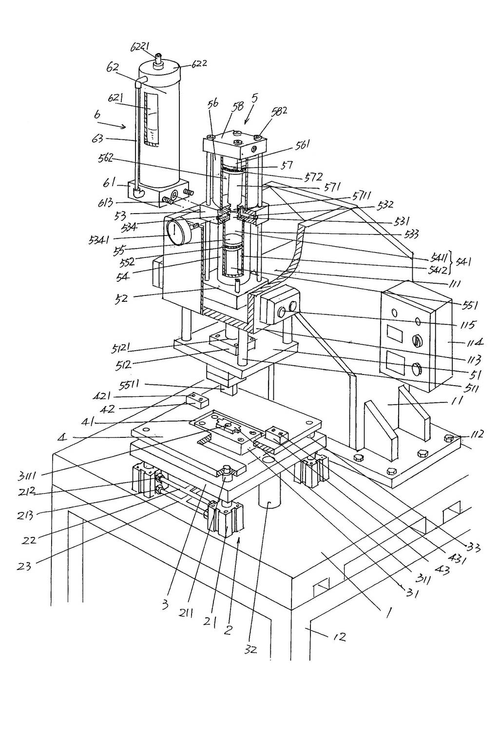
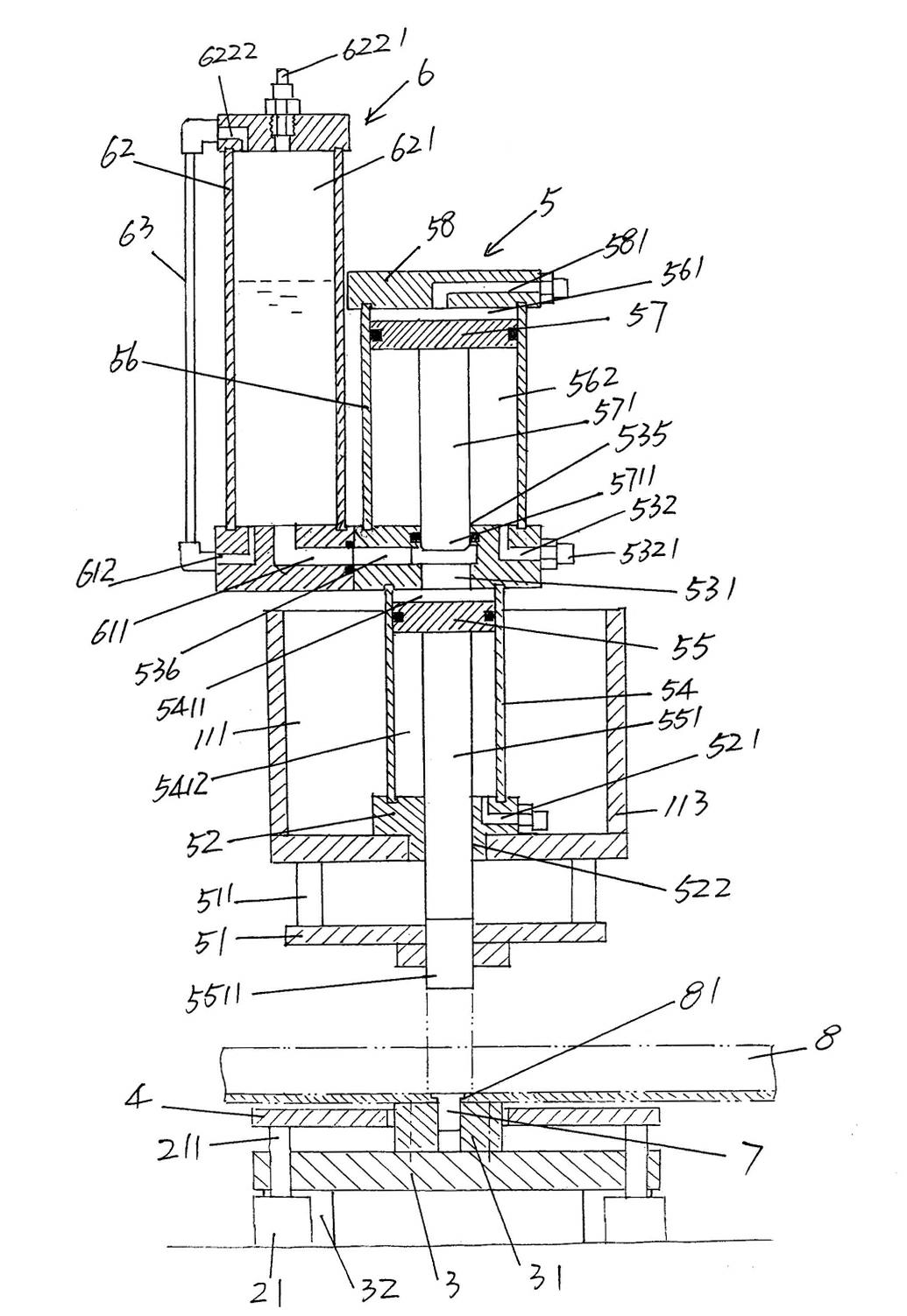
[0023] Please see figure 1 and figure 2 , a machine base platform 1 with support legs 12 (also called support feet) and set on the floor of the job site in use is given, on the surface of the machine base platform 1 facing upwards and on the machine base One side of the platform 1 is fixed with a base 11 by a first screw 112 , the overall shape of the base 11 is like the shape of Arabic numeral 7, and a base cavity 111 is formed.

[0024] The preferred but non-limiting structure of the ejector plate lifting mechanism 2 provided on the aforementioned base platform 1 is as follows: a group of action cylinders 21, a first communication pipe 22 and a second communication pipe 23 are included, and a group of action cylinders 21, a first communication pipe 22 and a second communication pipe 23 are included. The number of cylinders 21 is four, and they are fixed on the upward facing surface of the base platform 1 in the form of the Chinese character "口". There is one working ...


PUM


Abstract

The invention relates to a gas-liquid pressurized riveting machine and belongs to the technical field of riveting machines. The gas-liquid pressurized riveting machine comprises an engine base platform, a pushing plate lifting mechanism, a die base, a pulverizing plate, an instant pressurized pressure-riveting mechanism and a pressurized oil supplying mechanism, wherein an engine base is fixedly arranged on one side of the upward surface of the engine base platform in a using state and forms an engine base cavity; the pushing plate lifting mechanism is arranged on the engine base platform; the die base is fixed on the engine base platform; the pulverizing plate corresponds to the upper part of the die base and is connected with the pushing plate lifting mechanism, and the center of the pulverizing plate is provided with a die abdicating cavity; the instant pressurized pressure-riveting mechanism is positioned in the engine base cavity, fixed with the engine base and is above the position corresponding to the die abdicating cavity; and the pressurized oil supplying mechanism is connected with the instant pressurized pressure-riveting mechanism and communicated with a hydraulic pressure oil path of the instant pressurized pressure-riveting mechanism, a die is fixedly arranged on the die base, and a die core is arranged on the die. The gas-liquid pressurized riveting machine has the advantages that the simplified structure enables that the operation and maintenance are more convenient; and the replacement of dies is convenient, is good for reflecting the stability of actions as well as saving energy sources, and can reflect an ideal pressure-riveting effect.

Description

technical field [0001] The invention belongs to the technical field of riveting machines, and in particular relates to a gas-hydraulic pressurized riveting machine, which is used for riveting rivets to parts so as to complete a specific riveting process. Background technique [0002] The existing technology generally uses an electric-controlled punch to combine the rivet to the workpiece, that is to say, the riveting is completed through the punch. The large area is not conducive to saving the occupied space of the production site; the press riveting of the punch has limitations, for example, the riveting of some special parts is often powerless, that is, it is picky about the riveting parts of the riveted product; the rhythm of the riveting of the punch is slow and not conducive Improve efficiency. [0003] There is no lack of technical information about riveting machines in the published Chinese patent documents, such as "a multi-point rivetless automatic riveting machine...

Claims


Application Information

Patent Timeline
Patent Type & Authority Applications(China)
IPC IPC(8): B21J15/22
CPCB23P19/064
Inventor 高健顾建军谢利峰
Owner SOHBI CRAFT CHANGSHU
Why Eureka
Try Eureka