
Split type bearing bush centrifugal casting method

A centrifugal casting and split technology, applied to bearing components, shafts and bearings, mechanical equipment, etc., can solve problems such as poor quality of bearing pads, weak bonding, cracks, etc.

Active Publication Date: 2014-12-31
重庆新承航锐科技股份有限公司
View PDF3 Cites 0 Cited by
  • Summary
  • Abstract
  • Description
  • Claims
  • Application Information

AI Technical Summary

Problems solved by technology

[0002] The bearing pad is the contact part between the sliding bearing and the shaft, including the rigid structure shell and the anti-friction lining. It is generally formed by pouring the molten anti-friction material into the tile billet and solidifying it and then performing subsequent processing. The traditional bearing pad casting is two steel half The tiles are put together and the two halves of the tiles are clamped tightly with a steel belt to form a tile billet, and the tile billet can be tinned and poured, because the poured bearing bush lining forms a complete cylinder in the inner hole where the two half tiles are closed To form a whole with the two half-tiles, the bearing bush lining needs to be cut into two halves on the joint surface of the two half-tiles by a slotting machine or a sawing machine. Irregular cracks in the bearing pad lining under the action of stress, resulting in partial separation of the lining and the tile billet, weak bonding, and poor quality of the bearing pad

Method used


Image

  • Split type bearing bush centrifugal casting method
  • Split type bearing bush centrifugal casting method

Examples


Embodiment Construction

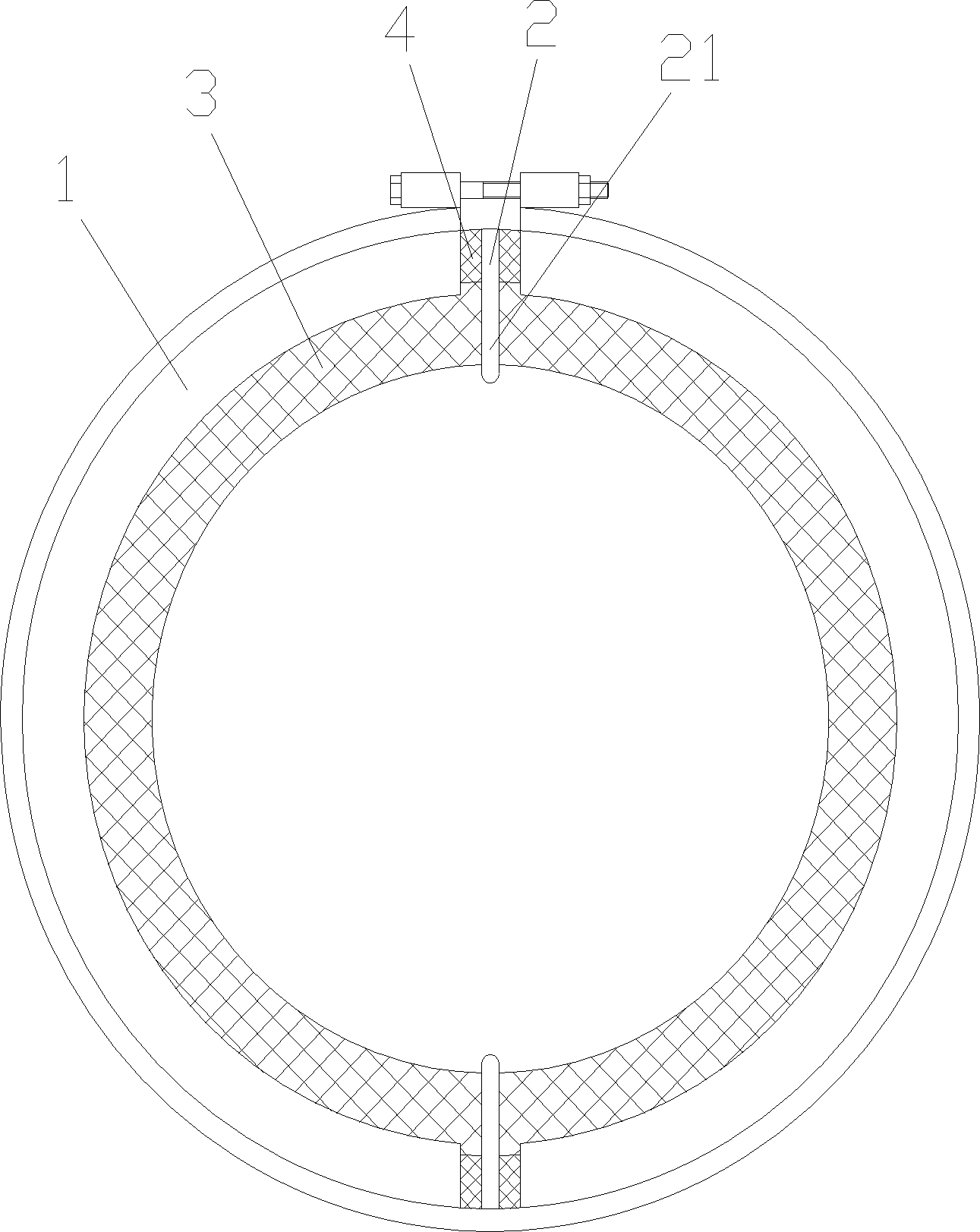
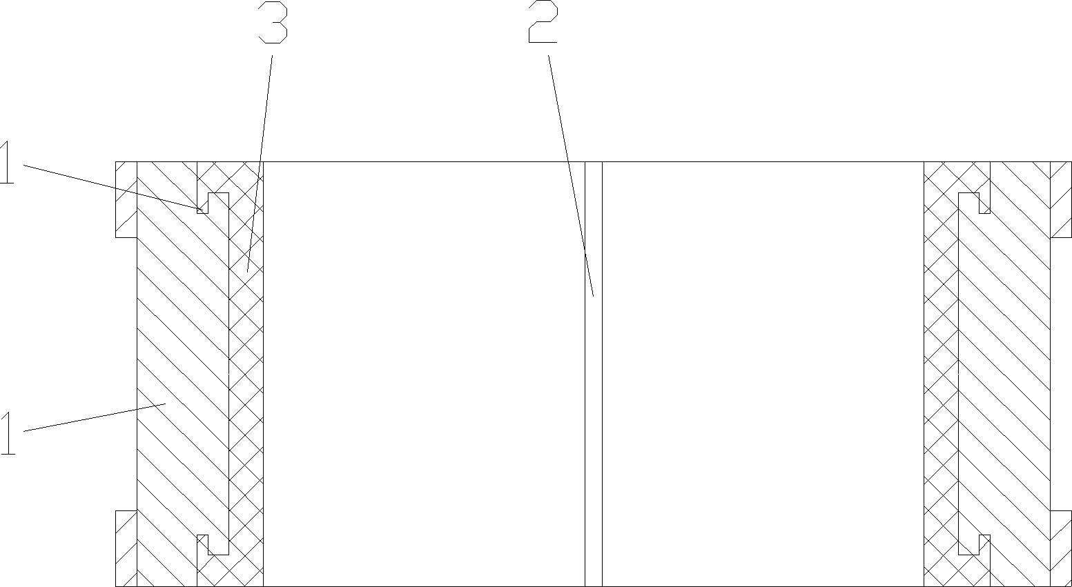
[0019] figure 1 A schematic diagram of the tile structure, figure 2 for figure 1 As shown in the figure: the centrifugal casting method of the split bearing bush in this embodiment includes the preparation of molten anti-friction material, treatment of the tile blank, centrifugal casting and subsequent processing. The tile blank 1 is fastened by two half tiles and then fixed made, specifically including the following steps:

[0020] a. preparing a molten anti-friction material for pouring into the interior of the tile 1 to form the lining 3;

[0021] b. An annular groove 11 is processed coaxially with the tile blank 1 on both ends of the tile blank 1. The side wall of the tile axis to ensure that the molten anti-friction material fills the annular groove 11 under the action of centrifugal force;

[0022] c. A spacer 2 is provided at the joint surface of the two half-tiles that are fastened together, and the spacer 2 extends toward the axis of the tile blank to form a leng...


PUM


Abstract

The invention discloses a split type bearing bush centrifugal casting method, which includes the steps of molten-state antifriction material preparation, bush billet treatment, centrifugal casting and subsequent machining. A bush billet is formed by fixing two fastened half bushes, and a bush billet treatment process includes the steps: machining annular grooves coaxial to the bush billet on two end faces of the bush billet, enabling each of two side walls of each annular groove to be low inside and high outside, arranging a spacer on a jointing face of the two half bushes which are integrally fastened, and enabling the spacer to extend along the axis of the bush billet to form a partition with the radial length along the bush billet not smaller than the radial thickness of a lining formed by pre-casting. Subsequent machining of the split type bearing bush centrifugal casting method only needs to turn two end faces of a bush body formed after casting, two split half bushes naturally form two bearing bushes without machining of a slotting machine or a sawing machine, Babbitt metal is low in internal stress generated by means of subsequent machining and is firm in jointing with the bush billet, bearing bush forming quality can be guaranteed, subsequent machining difficulty is low, workload is less and machining cost is low.

Description

technical field [0001] The invention relates to a bearing bush centrifugal casting method, in particular to a split bearing bush centrifugal casting method with good molding quality and convenient subsequent processing. Background technique [0002] The bearing pad is the contact part between the sliding bearing and the shaft, including the rigid structure shell and the anti-friction lining. It is generally formed by pouring the molten anti-friction material into the tile billet and solidifying it and then performing subsequent processing. The traditional bearing pad casting is two steel half The tiles are put together and the two halves of the tiles are clamped tightly with a steel belt to form a tile billet, and the tile billet can be tinned and poured, because the poured bearing bush lining forms a complete cylinder in the inner hole where the two half tiles are closed To form a whole with the two half-tiles, the bearing bush lining needs to be cut into two halves on the ...

Claims


Application Information

Patent Timeline
Patent Type & Authority Patents(China)
IPC IPC(8): B22D13/00B22D19/08B22D19/16F16C33/02F16C33/14
Inventor 詹国平
Owner 重庆新承航锐科技股份有限公司
Learn More