Hydraulic assembly of electro-hydraulic switch machine

A technology of hydraulic assembly and switch machine, which is used in hydraulic equipment for operating turnouts or line interrupters, railway car body parts, railway signals, etc., can solve the problem of increased sealing difficulty, manual labor, and difficulty in coordination and synchronization. question

Active Publication Date: 2012-07-18
TIANJIN HUIHUANG LUYANG TECH
View PDF4 Cites 5 Cited by
  • Summary
  • Abstract
  • Description
  • Claims
  • Application Information

AI Technical Summary

Problems solved by technology

Such a hydraulic drive mechanism has some disadvantages: (1) It is difficult to coordinate and synchronize when multiple switch machines pull the point rail or the core rail. In this way, the length of the point rail or core rail also increases
Since the oil supply start and end times of each point machine are inconsistent, it is difficult for multiple point machines to be synchronized
The size of the switch machine is large, and the problem of the hydraulic drive mechanism has a great impact on the large size. Most of the existing switch machines use hydraulic devices to directly drive the moving parts that pull the point rail or the center rail. In addition, there are connecting pipelines, pipe fittings and corresponding sealing devices in the hydraulic cylinder device in the hydraulic drive mechanism, which will occupy a large space, which will make the length of the switch machine at least exceed 700mm
The size of the equipment is large, which cannot meet the needs of installing the switch machine in the middle of the track, especially in the subway, without occupying the space beside the track.
(2) Tight sealing cannot be achieved, and the hydraulic station with separate structure makes sealing more difficult
The manual mechanism of the switch machine in the prior art generally manually shakes the m

Method used


Image

  • Hydraulic assembly of electro-hydraulic switch machine
  • Hydraulic assembly of electro-hydraulic switch machine
  • Hydraulic assembly of electro-hydraulic switch machine

Examples


Embodiment Construction

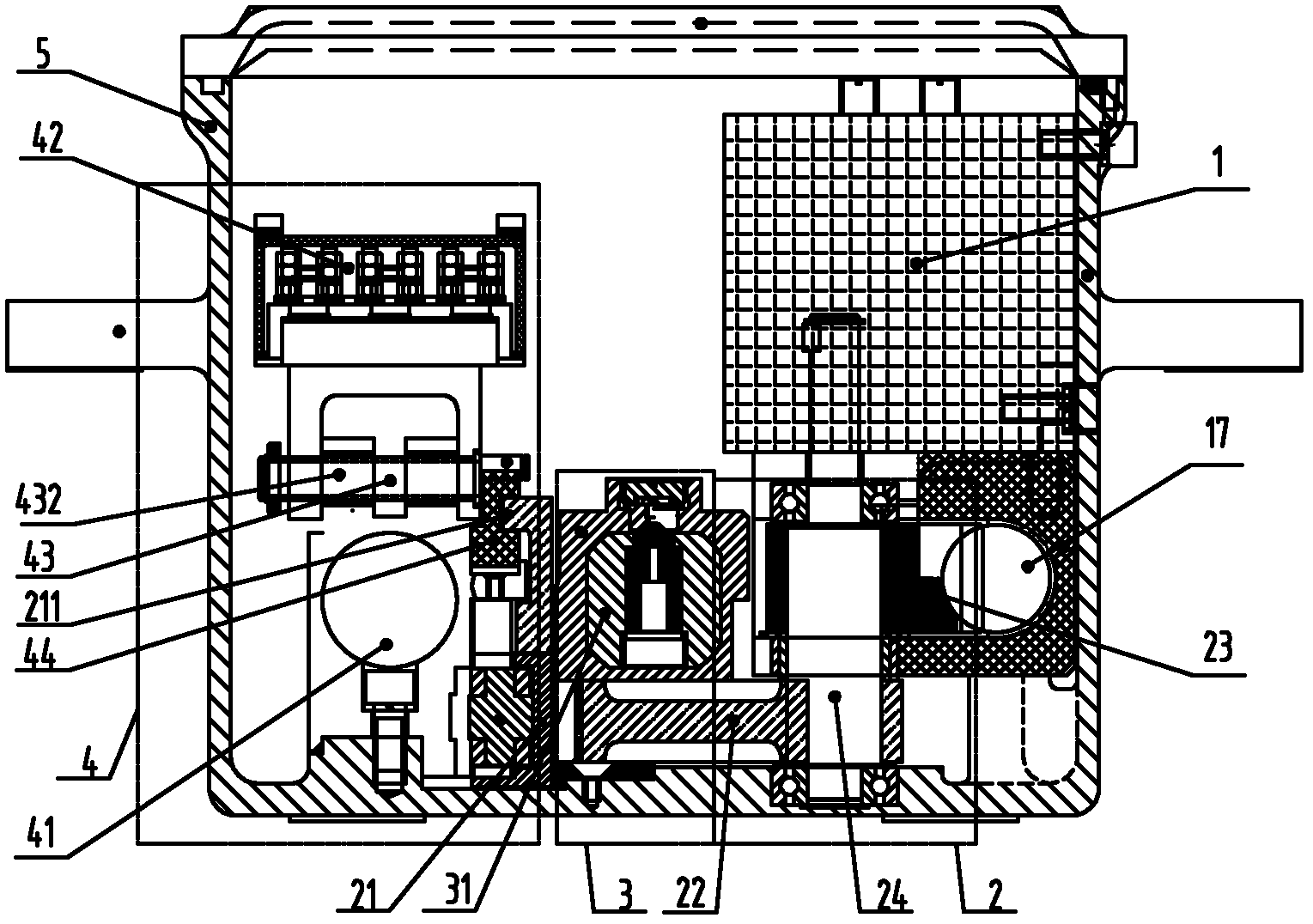
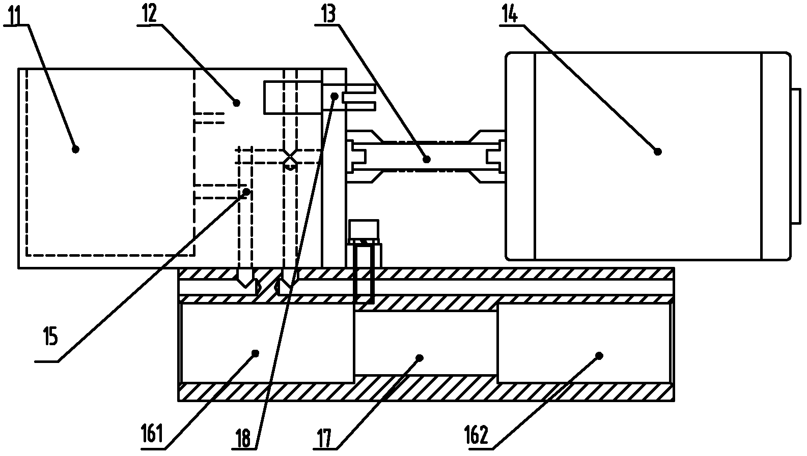
[0023] Such as figure 1 and figure 2 As shown, an electro-hydraulic switch machine is provided, including an electric motor 14, a hydraulic assembly 1, a transmission mechanism 2, a conversion locking mechanism 3 and an indication mechanism 4, which are connected to each other.

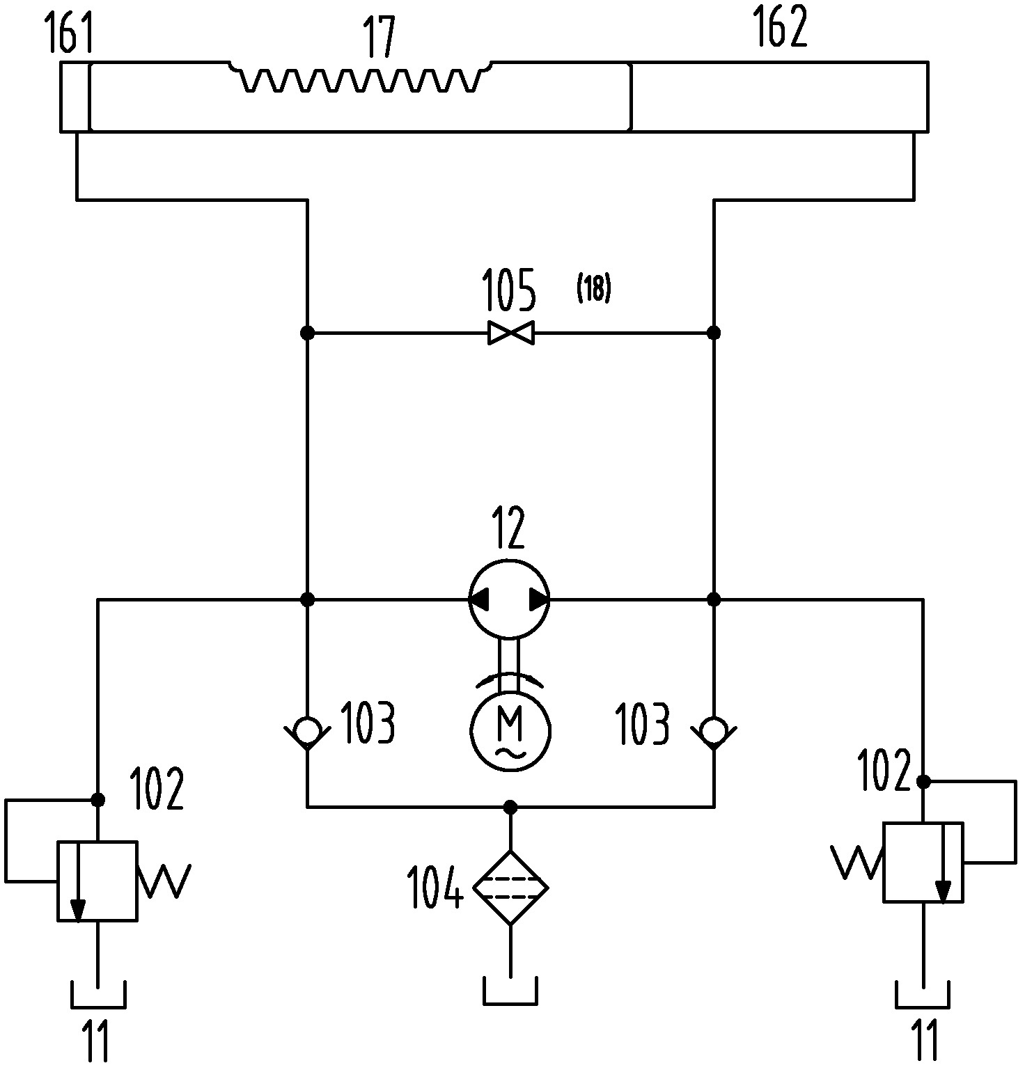
[0024] Such as figure 2 As shown, the oil cylinder 16 in the hydraulic assembly 1 is a double-acting oil cylinder, and the oil cylinder includes a left oil cylinder 161 and a right oil cylinder 162. A piston is respectively arranged on both sides of a piston rod 17 in the middle, and the two pistons are respectively placed In the two oil cylinders, the oil cylinder body is fixed and the piston moves; the three-phase AC motor 14 is connected to the oil pump through the electric motor oil pump transmission shaft 13, and the oil pump is connected to the oil tank 11 and the oil cylinder 16 through the integrated oil pipeline 15. The piston rod in the hydraulic assembly 1 is processed into a rack tooth...


PUM


Abstract

The invention provides a hydraulic assembly of an electro-hydraulic switch machine, which comprises an oil tank, an oil pump and an oil cylinder, which are connected together through an oil pipeline, and a piston is arranged in the oil cylinder. The hydraulic assembly is characterized in that the cylinder body of the oil cylinder is fixed on a rack, and the piston therein moves; and a gear rack tooth form is processed on the piston rod of the piston to form a piston gear rack. The oil tank, the oil pump and the oil cylinder in the hydraulic assembly are fixedly connected together, and the oil pipeline therebetween is arranged in an oil way block. The hydraulic assembly provided in the invention can guarantee the movement coordination, effectively avoid leakage and guarantee a more compact structure of the switch machine.

Description

technical field [0001] The invention relates to an electrohydraulic switch machine, in particular to a hydraulic assembly for the electrohydraulic switch machine. Background technique [0002] The electro-hydraulic switch machine is a special equipment for centralized control of switching switches in railways, underground railways, and urban rail transit stations. It can convert and lock the point rail or center rail of the switch, and at the same time give the position indication of the corresponding switch point rail or center rail. [0003] The electro-hydraulic switch machines in the prior art include electric motors, hydraulic stations, switching and locking mechanisms, and display mechanisms, which are connected to each other; most of the existing electro-hydraulic switch machines are directly connected to the pulling point rails or cores through hydraulic cylinders. The moving parts of the rail, the hydraulic cylinder device in the hydraulic drive mechanism, the hydr...

Claims


Application Information

Patent Timeline
IPC IPC(8): B61L5/04
Inventor 吴学文何家林张建铭李纪勇宋明惠关雪飞马天宇
Owner TIANJIN HUIHUANG LUYANG TECH
Why Eureka
Try Eureka