Manufacturing method for long life electroplated diamond bit

A technology of electroplating diamonds and manufacturing methods, which is applied to drill bits, electrolytic coatings, earthwork drilling and mining, etc. It can solve the problems that the diameter protection effect of drill bits cannot meet the requirements, the height of the electroplating working layer of drill bits is limited, and the service life of drill bits is reduced. Good performance, easy operation, and improved service life

Active Publication Date: 2012-07-18
WUHAN WAN BANG LASER DIAMOND TOOLS
View PDF4 Cites 15 Cited by
  • Summary
  • Abstract
  • Description
  • Claims
  • Application Information

AI Technical Summary

Problems solved by technology

The previous core drilling technology can no longer meet the requirements of modern deep drilling, and the wireline core drilling technology must be vigorously promoted. This requires high-efficiency, long-life diamond drills to match it, otherwise, the wireline core drilling technology cannot be used. The advantages of core drilling will inevitably lead to the consequences of greatly extending the construction period and significantly increasing drilling costs
[0003] However, the advantage of ordinary electroplated diamond drill bits is high drilling efficiency, but the service life of the drill bit is relatively short.
This has both advantages for deep hole and wireline core drilling, that is, high drilling efficiency, and disadvantages, that is, the service life of the drill bit is reduced due to the poor diameter protection effect of the drill bit and the low working layer

Method used


Image

  • Manufacturing method for long life electroplated diamond bit
  • Manufacturing method for long life electroplated diamond bit
  • Manufacturing method for long life electroplated diamond bit

Examples


Embodiment Construction

[0028] The present invention will be further described below in conjunction with accompanying drawing and embodiment:

[0029] Two-time electroplating forming process technology of drill bit:

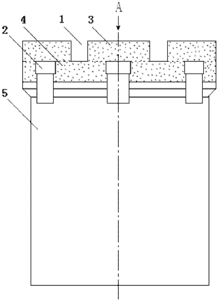
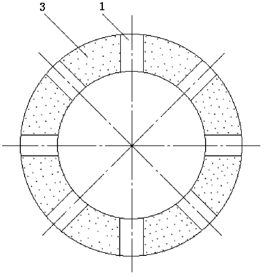
[0030] The drill bit steel substrate 5 that has been treated before plating is electroplated in the tank. After 25 minutes of electroplating, put on the inner and outer diameter molds, and add diamond composite plating on the bottom lip of the drill bit. After the coating height of the upper working layer 4 reaches the requirement of 5mm, use the conductive nozzle Plug ( image 3 ) to replace the ordinary nozzle plug "bridge", and place an ordinary nozzle plug in the middle of the upper working layer 4 at the same time; continue to add diamond composite plating to the lower working layer 3 of the drill bit until the lower working layer 3 of the drill bit reaches the design height of 8mm.

[0031] After the upper and lower working layers of the electroplated diamond drill bit are all com...


PUM


Abstract

The invention discloses a manufacturing method for a long life electroplated diamond bit. A working layer is designed into upper and lower double working layers which are separated by upper and lower waterways. The manufacturing method adopts a secondary feeding groove secondary forming electroplating process and comprises the following steps: electroplating the upper working layer of the electroplated bit by adopting conductive water gap plug 'bridging', adding a common water gap plug in the middle of the working layer and continuously electroplating the lower working layer; and entering inner and outer gauge protection layers of a secondary feeding groove electroplated bit after the operation of electroplating the working layers meets the requirement. The electroplating process comprises the steps of discharging the bit with the electroplated working layers out of the groove, cleaning completely, soaking and preplating in activating preplating liquid, electroplating inner and outer diameters of the electroplating bit in a normal electroplating groove and finishing manufacturing of the bit. The method is unique. According to the method, the effective working layers of the bit are high, the gauge protection effect of the bit can be effectively improved and the adaptability of the bit to the rock stratum is improved, so that the drilling effect of the bit can be obviously improved and the requirements of deep exploration and wire line coring drilling can be met well.

Description

technical field [0001] The invention relates to a method for manufacturing a drill bit used in the field of geological engineering, in particular to a method for manufacturing a long-life electroplated diamond drill bit. Background technique [0002] Since entering the 21st century, my country's geological exploration, scientific drilling and deep ore prospecting have developed rapidly. The previous core drilling technology can no longer meet the requirements of modern deep drilling, and the wireline core drilling technology must be vigorously promoted. This requires high-efficiency, long-life diamond drills to match it, otherwise, the wireline core drilling technology cannot be used. The advantages of core drilling will inevitably lead to the consequences of greatly extending the construction period and significantly increasing drilling costs. [0003] However, the advantage of ordinary electroplated diamond drill bits is high drilling efficiency, but the service life of t...

Claims


Application Information

Patent Timeline
Patent Type & Authority Applications(China)
IPC IPC(8): C25D15/00C25D7/00E21B10/02
Inventor 叶宏煜杨凯华
Owner WUHAN WAN BANG LASER DIAMOND TOOLS
Why Eureka
Try Eureka