Mechanical booster clutch of electrically controlled silicone oil

A technology of mechanical supercharging and clutch, applied in the field of clutch, to achieve the effect of small external influence, high control precision and fast response

Inactive Publication Date: 2012-07-18
SINO TRUK JINAN POWER
View PDF0 Cites 3 Cited by
  • Summary
  • Abstract
  • Description
  • Claims
  • Application Information

AI Technical Summary

Problems solved by technology

However, it is necessary to solve the problem of the conversion of the working state of the supercharger

Method used


Image

  • Mechanical booster clutch of electrically controlled silicone oil
  • Mechanical booster clutch of electrically controlled silicone oil

Examples


Embodiment Construction

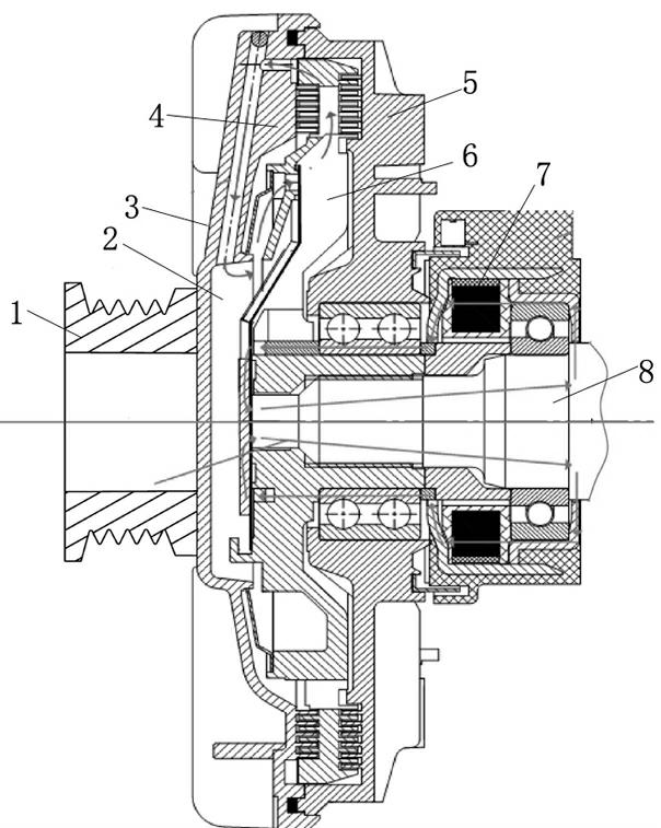
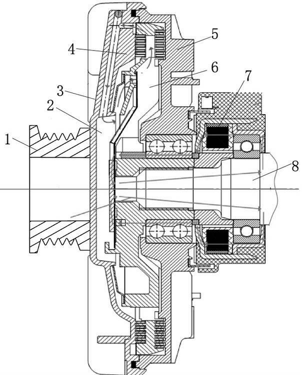
[0016] Such as figure 1 As shown, an electronically controlled silicon oil mechanical supercharged clutch includes a hydraulic coupling, and the hydraulic coupling includes a drive shaft 1 driven by a crankshaft, a pump wheel 5, a rotating casing 3, and a turbine wheel axially opposite to the pump wheel 1. Drive the driven shaft 8 of the supercharger, the flow channel 6 formed between the turbine and the pump wheel, and the auxiliary oil chamber 2 formed between the rotating housing and the outer side of the turbine. The auxiliary oil chamber communicates with the flow channel at the outer edge, and the flow channel Partially filled with silicone oil, the inner side of the upper blade area of ​​the turbine is provided with an oil hole connecting the auxiliary oil chamber and the flow channel and a valve to control the opening of the oil hole.

[0017] When the oil hole is closed, the driven shaft does not move; as the opening of the valve increases, the speed of the driven sh...


PUM


Abstract

The invention provides a mechanical booster clutch of electrically controlled silicone oil. The mechanical booster clutch comprises a fluid coupling, wherein the fluid coupling comprises a driving shaft which is driven by a bent shaft, a pump wheel, a turning shell, a turbine which is axially opposite to the pump wheel, a driven shaft which is used for driving a mechanical booster, a flow channel formed between the turbine and the pump wheel, and an auxiliary oil chamber formed between the turning shell and the outer side of the turbine, wherein the auxiliary oil chamber is communicated with the flow channel on the outer edge; a quantitative part in the flow channel is filled with the silicone oil; and the inner side of a vane area on the turbine is provided with an oil hole and a valve; the oil hole is used for communicating the auxiliary oil chamber and the flow channel; and the valve is used for controlling the aperture of the oil hole. The mechanical booster clutch of electrically controlled silicon oil disclosed by the invention controls the flow of the silicon oil in the auxiliary oil chamber entering the flow channel by controlling the aperture of the valve, so as to control the filling degree of the silicone oil in the flow channel; and the connection, isolation and stepless speed regulation of the mechanical booster can be realized via the high viscosity characteristic of the silicone oil.

Description

technical field [0001] The invention relates to a clutch, in particular to an electronically controlled silicon oil mechanical supercharged clutch. Background technique [0002] At present, internal combustion engine supercharging technology mainly adopts exhaust gas turbocharger or mechanical supercharger. The exhaust gas turbocharger is driven by the high-temperature and high-pressure exhaust gas discharged from the internal combustion engine, and the supercharger is directly driven by the crankshaft of the internal combustion engine. Supercharging helps with torque output at low revs but limited power output at high revs, while exhaust turbocharging has strong power output at high revs but not enough at low revs. In view of the characteristics of the exhaust gas turbocharger and the supercharger, it is necessary to use the exhaust gas turbocharger instead of the supercharger in the high-speed stage to solve the problem of low-speed torque output and high-speed power ou...

Claims


Application Information

Patent Timeline
Patent Type & Authority Applications(China)
IPC IPC(8): F02B39/10
Inventor 卢永信罗列冠朱舸珩蔡毅
Owner SINO TRUK JINAN POWER
Why Eureka
Try Eureka