Back lighting device and liquid crystal display device

A technology for backlighting and grating, applied in optics, nonlinear optics, instruments, etc., can solve problems such as unfavorable LCD thinning, and achieve the effects of improving light guide uniformity, simplifying design, and improving light energy utilization efficiency.

Inactive Publication Date: 2014-07-16
SUZHOU UNIV
View PDF2 Cites 1 Cited by
  • Summary
  • Abstract
  • Description
  • Claims
  • Application Information

AI Technical Summary

Problems solved by technology

However, this method usually requires the use of an achromatic 1 / 4 wave plate to convert the polarization state, and too many optical films are not conducive to the thinning of LCD

Method used


Image

  • Back lighting device and liquid crystal display device
  • Back lighting device and liquid crystal display device
  • Back lighting device and liquid crystal display device

Examples


Embodiment Construction

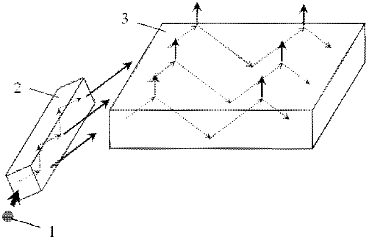
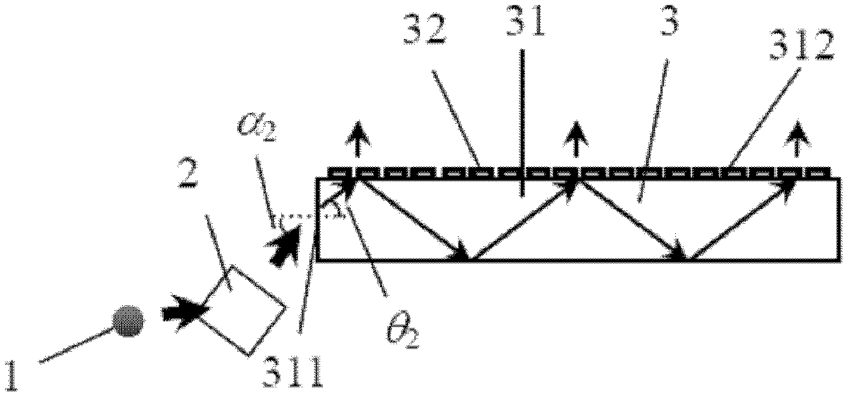
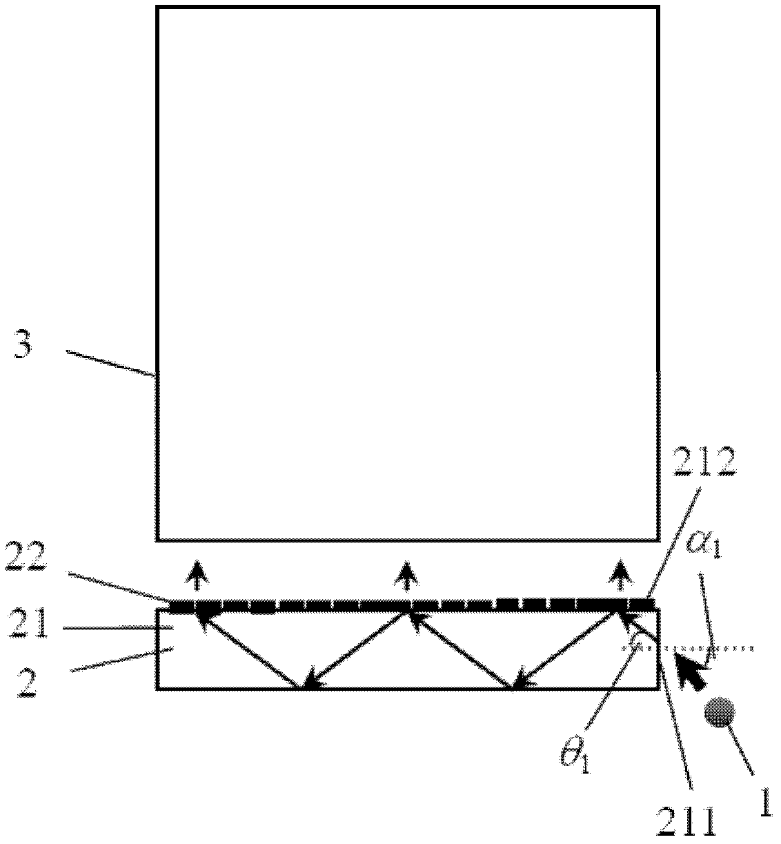
[0035] The purpose of the present invention is based on: how to make the final outgoing light still maintain a linearly polarized state during the process of converting the point light source into a surface light source; how to make the surface light source have good uniformity, that is, the design of the light guide strip and light guide film. .

[0036] In order to enable those skilled in the art to better understand the technical solutions in the present application, the technical solutions in the embodiments of the present application will be clearly and completely described below in conjunction with the drawings in the embodiments of the present application. Obviously, the described The embodiments are only some of the embodiments of the present application, but not all of them. Based on the embodiments in this application, all other embodiments obtained by persons of ordinary skill in the art without creative efforts shall fall within the scope of protection of this appl...


PUM


Abstract

The invention discloses a back lighting device, which comprises a point light source, a rectangular light guide strip and a tabular light guide film. The light guide strip comprises a first light entering surface and a first light exiting surface, linearly polarized light enters from the first light entering surface, and linearly polarized parallel light exits through the first light exiting surface. The light guide film comprises a second light entering surface and a second light exiting surface, the linearly polarized parallel light enters from the second light entering surface and exits through the second light exiting surface. The invention further discloses a liquid crystal display device. The back lighting device is high in light energy utilization rate, light guide uniformity is improved, and the obtained liquid crystal display device is light and thin.

Description

technical field [0001] The invention relates to a backlight illuminating device using a linearly polarized point light source and a liquid crystal display device using the backlight illuminating device. Background technique [0002] With the rapid development of liquid crystal display (LCD), it occupies an increasingly important position in the field of flat panel display. [0003] Since the liquid crystal itself does not emit light, the LCD needs a backlight module to provide lighting, that is, the light emitted by the light source (LED, CCFL, etc.) Form a uniform surface light source, and then enter the liquid crystal layer through a polarizing film and a color filter. However, in such a backlight module, the utilization efficiency of light energy is often very low, only about 5%. Wherein the light loses more than 50% of its energy when passing through the polarizing film. [0004] In order to reduce the loss of light energy when natural light is converted into polarize...

Claims


Application Information

Patent Timeline
Patent Type & Authority Patents(China)
IPC IPC(8): G02F1/13357
Inventor 张伟彭长四顾小勇刘维萍王艳艳张锋元磊
Owner SUZHOU UNIV
Why Eureka
Try Eureka