
Evaluating method and evaluating device for surface shape
A technology of surface shape and evaluation method, which can be used in measurement devices, optical devices, instruments, etc., and can solve problems such as inability to evaluate surface shape correctly.
- Summary
- Abstract
- Description
- Claims
- Application Information
AI Technical Summary
Problems solved by technology
Method used
Image

Examples
Embodiment approach 1
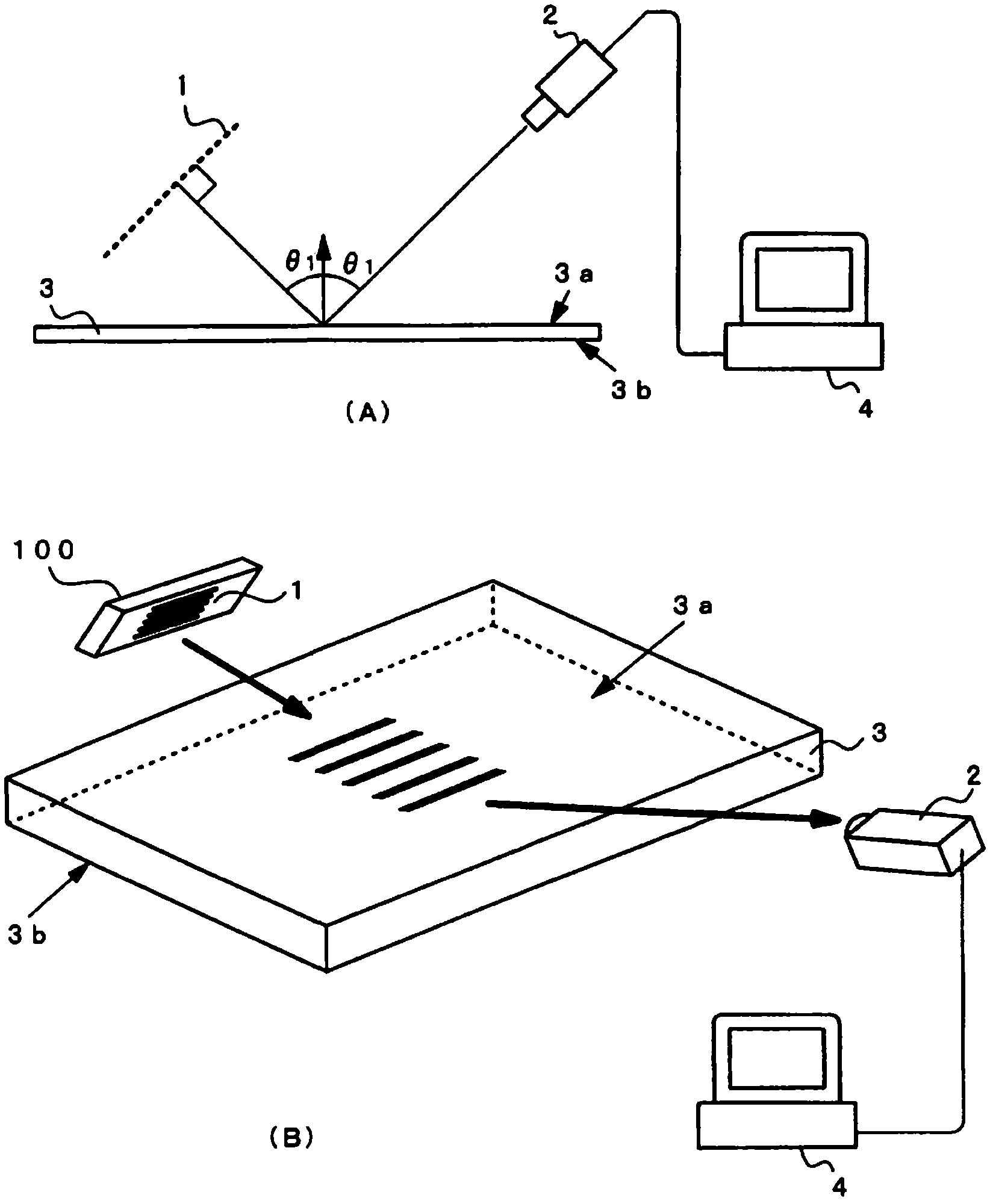
[0088] First, the premise of the evaluation method of the surface shape used in this embodiment will be described. Figure 4 It is an explanatory diagram for explaining the evaluation method of the surface shape.
[0089] The light from the light source 100 passing through the stripe pattern 1 is irradiated onto the object 3 to be evaluated, and the reflected light from the surface 3 a of the object to be evaluated 3 is received by the imaging element of the CCD camera 2 . In this specification, "the light from the light source 100 passing through the stripe pattern 1" means the light passing through the stripe pattern 1, and the light irradiated through the stripe pattern 1 will be referred to as "irradiating the stripe pattern 1" below.
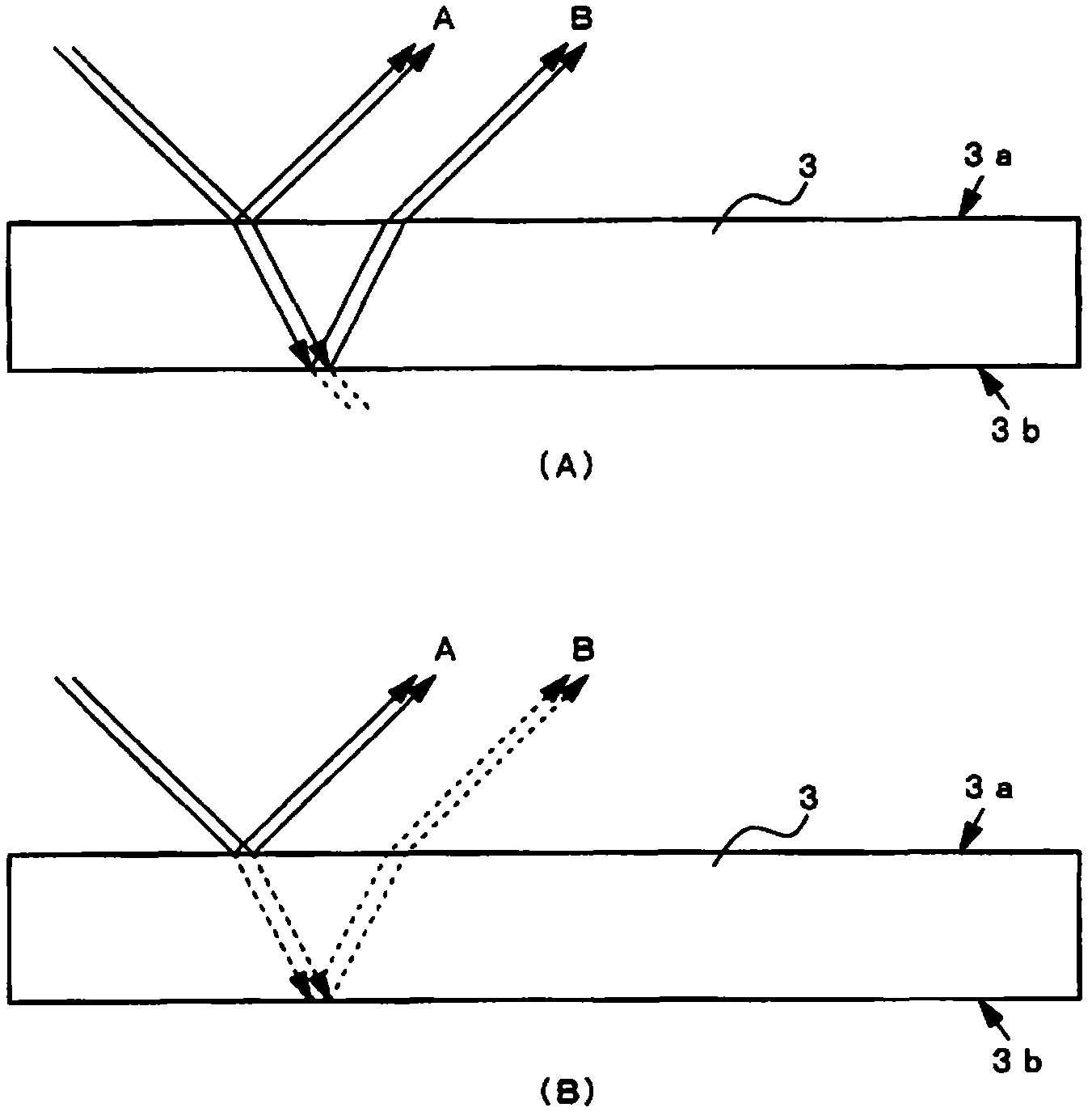
[0090] In addition, in this embodiment, the reflected light from the back surface 3b of the object 3 to be evaluated hardly enters the CCD camera 2 .
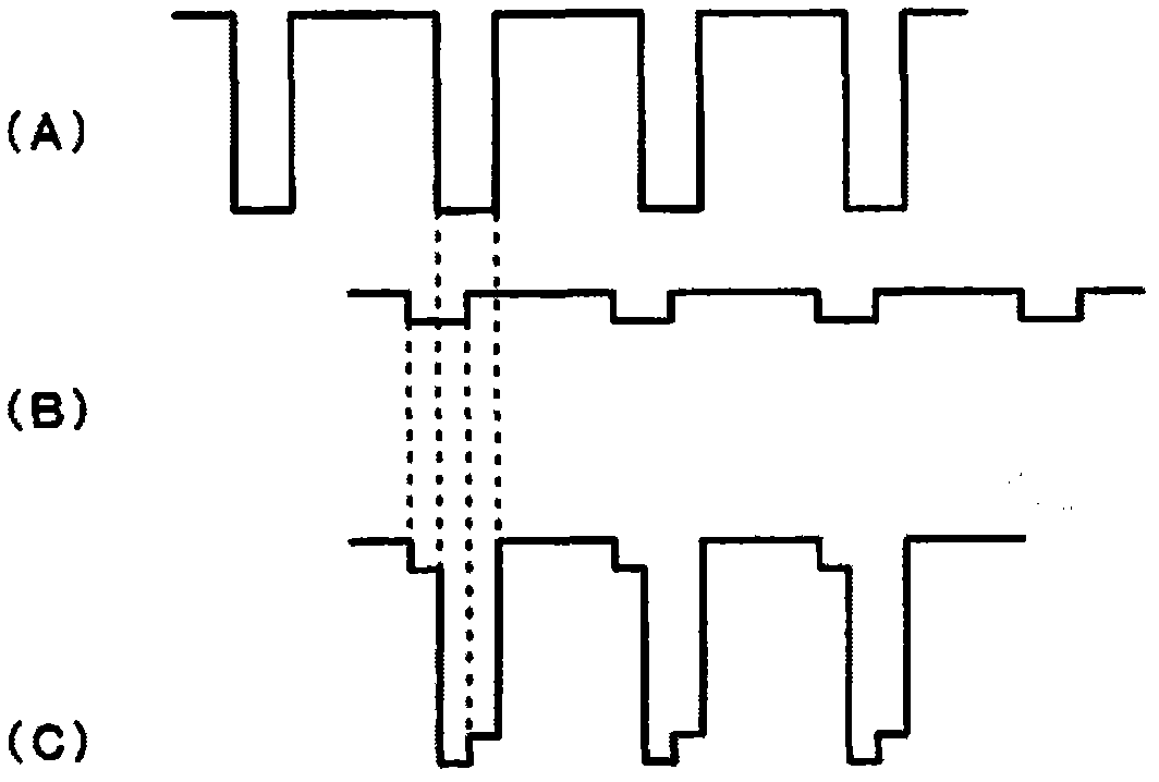
[0091] The computing device 4 evaluates the surface shape based on an electric signal (...
example 1
[0122] Next, the results obtained by comparing the measurement results of the contact measuring machine with the evaluation of the evaluation device of the present embodiment will be described. Figure 10 (A) to (E) of 10 show the results of measuring the surface shape of one surface of each of the cross-sections of five glass plates as samples A to E with a contact measuring machine. Each of samples A to E is a glass plate having a thickness of 0.7 mm and a side length of 300 mm. In addition, each sample A to E which is the object to be evaluated has moires with a half-pitch of about 10 mm to 15 mm.
[0123] Figure 11 (A) to (E) of 11 show the output of the averaging circuit 44 under the condition that the optical axis forms an inclination angle of 30° with samples A to E, a f25 lens is used in the CCD camera 2 , and the aperture is F16. The used stripe pattern 1 is set to have a white-black pitch of 6 mm (1 / f=6 mm), a pixel of more than 1 mm on the sample surface, and a p...
Embodiment approach 2
[0128] Figure 13 It is a configuration diagram showing a configuration example of the second embodiment of the surface shape evaluation device of the present invention. In addition, in this embodiment, a waviness shape measurement device is shown as a surface shape evaluation device. Such as Figure 13 As shown, the measurement device includes a CCD camera 2 and computing devices 4 such as a computer. The CCD camera 2 receives light reflected from a moving bright spot 6 and is reflected on the surface of a glass plate as the object to be evaluated 3 to form a reflection image. The device 4 inputs the locus of the reflected image formed by the CCD camera 2, and the calculation device 4 calculates the corrugation shape.
[0129] In addition, although the CCD camera 2 is exemplified here, instead of the CCD camera 2 , any type of camera such as an area scan camera, a line scan camera, a video camera, or a still camera can be used. In addition, any light receiving device can b...
PUM
| Property | Measurement | Unit |
|---|---|---|
| Wavelength | aaaaa | aaaaa |
Abstract
Description
Claims
Application Information