Millimeter-wave\submillimeter-wave near-field amplitude and phase measuring method

A submillimeter wave and millimeter wave technology, applied in the field of millimeter wave\submillimeter wave near-field detection, to achieve the effect of improving test efficiency

Inactive Publication Date: 2012-07-18
BEIHANG UNIV
View PDF1 Cites 21 Cited by
  • Summary
  • Abstract
  • Description
  • Claims
  • Application Information

AI Technical Summary

Problems solved by technology

This test method doubles the test time and data volume and relies on recovery algorithms

Method used


Image

  • Millimeter-wave\submillimeter-wave near-field amplitude and phase measuring method
  • Millimeter-wave\submillimeter-wave near-field amplitude and phase measuring method
  • Millimeter-wave\submillimeter-wave near-field amplitude and phase measuring method

Examples


Embodiment Construction

[0022] The present invention will be described in detail below in conjunction with the accompanying drawings and specific embodiments.

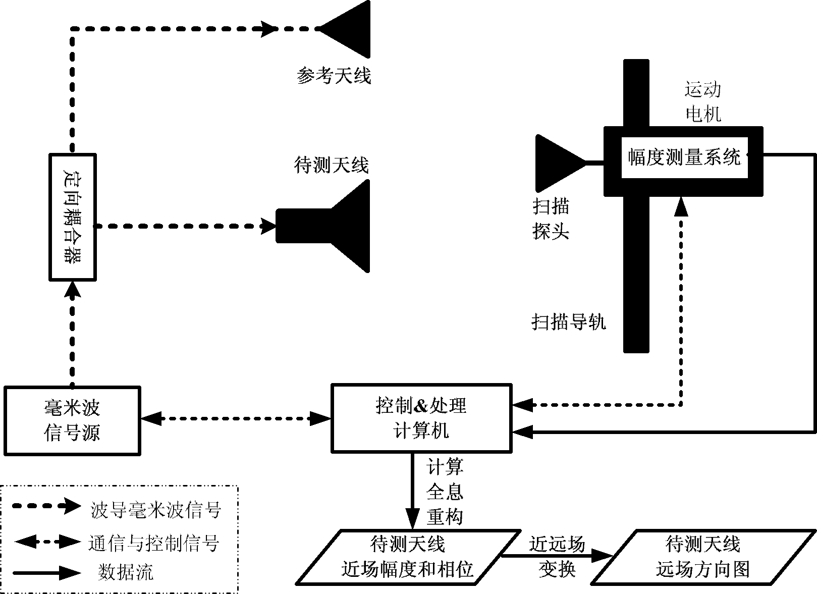
[0023] Such as figure 1 The basic principle shown is that the signal excited by the same source (coherence) is distributed to the antenna under test and the reference antenna through the directional coupler and sent out. The spatial interference field between the two in the scanning area (plane, cylinder or sphere) is the scanning probe received, and its amplitude is measured by the measurement system. The control and processing of the measurement system are implemented by a computer, and finally the near-field amplitude and phase of the antenna under test are reconstructed through virtual signal processing calculations.

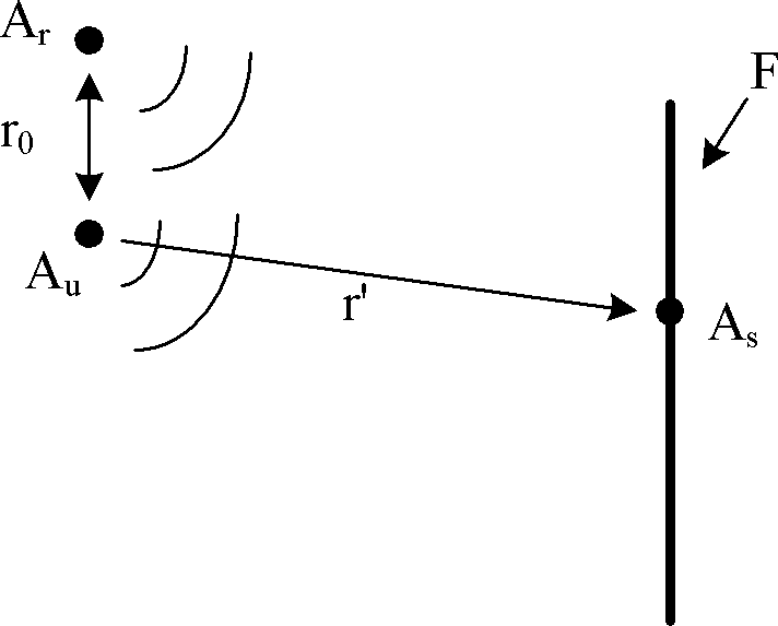
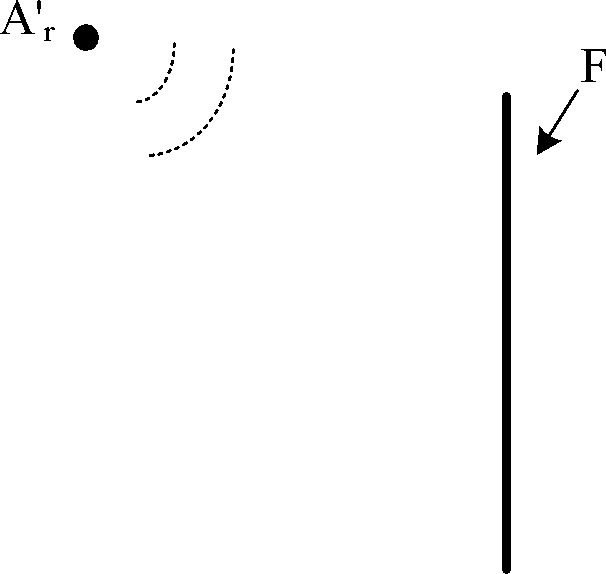
[0024] Such as figure 2 As shown, A u is the antenna under test, A r is the reference antenna, A s Antenna for the scanning probe. The spatial interference field in the scanning near-field area is formed by the coher...


PUM


Abstract

The invention relates to a millimeter-wave\submillimeter-wave near-field amplitude and phase measuring method, and the base technical principle of the method is as follows: a same source-excited signal is distributed in a to-be-measured antenna and a reference antenna by a directional coupler and sent out, the spatial interference fields of the two in a scanning area are received by a scanning probe, and the amplitudes of the spatial interference fields are measured by a measuring system. Through carrying out virtual signal processing on the amplitudes of the spatial interference fields, the near-field amplitude and phase of the to-be-measured antenna are calculated and reconstructed, and if necessary, a far-field directional diagram can be obtained through far and near field transformation processing.

Description

technical field [0001] The invention relates to the technical field of millimeter wave / submillimeter wave near-field detection, which is mainly used in indoor and outdoor millimeter wave / submillimeter wave near-field detection, and can detect the level amplitude and phase distribution of millimeter wave / submillimeter wave antennas , the far-field pattern of the millimeter-wave\submillimeter antenna can also be obtained by performing near-far field transformation on the amplitude and phase information obtained from the near-field test. Background technique [0002] The millimeter wave / submillimeter wave band is between light waves and radio waves, the frequency range is 30-300GHz, and the wavelength is 10-1mm, which is shorter than the microwave band. Millimeter-wave antennas can easily obtain high-gain narrow beams, and signals are not easily interfered and intercepted; millimeter-wave components are easy to integrate, and the system has the advantages of small size and ligh...

Claims


Application Information

Patent Timeline
Patent Type & Authority Applications(China)
IPC IPC(8): G01R29/08G01R29/10
Inventor 李志平武建华许鼎王正鹏
Owner BEIHANG UNIV
Why Eureka
Try Eureka