Jig for aging tests

A technology of aging testing and fixtures, which is applied in the direction of measuring electricity, measuring devices, measuring electrical variables, etc., and can solve problems such as cumbersome operation, unfavorable production and processing, and inaccurate positioning.

Active Publication Date: 2012-07-18
DONGGUAN GUANJIA ELECTRONICS EQUIP
View PDF7 Cites 6 Cited by
  • Summary
  • Abstract
  • Description
  • Claims
  • Application Information

AI Technical Summary

Problems solved by technology

However, its disadvantages are: on the one hand, during operation, it is necessary to move the electrical contact plate to the position where it fits with the end face of the product fixing seat, and then fix the electrical contact plate so that the electrical contact terminal group on the electrical contact plate Electrically connect with the interface of the electronic product, and then electrically connect the signal interface device with the test equipment to complete an aging test of the electronic product
The process is cumbersome to operate, and during use, the electrical contact plate is easily damaged due to repeated sliding back and forth, resulting in poor contact or inaccurate positioning, thereby reducing the efficiency of the aging test; on the other hand, before the aging test of electronic products, the fixture It is still necessary to connect the electronic load, and the structure of the jig is complicated, which is not conducive to production and processing

Method used


Image

  • Jig for aging tests
  • Jig for aging tests
  • Jig for aging tests

Examples


Embodiment 1

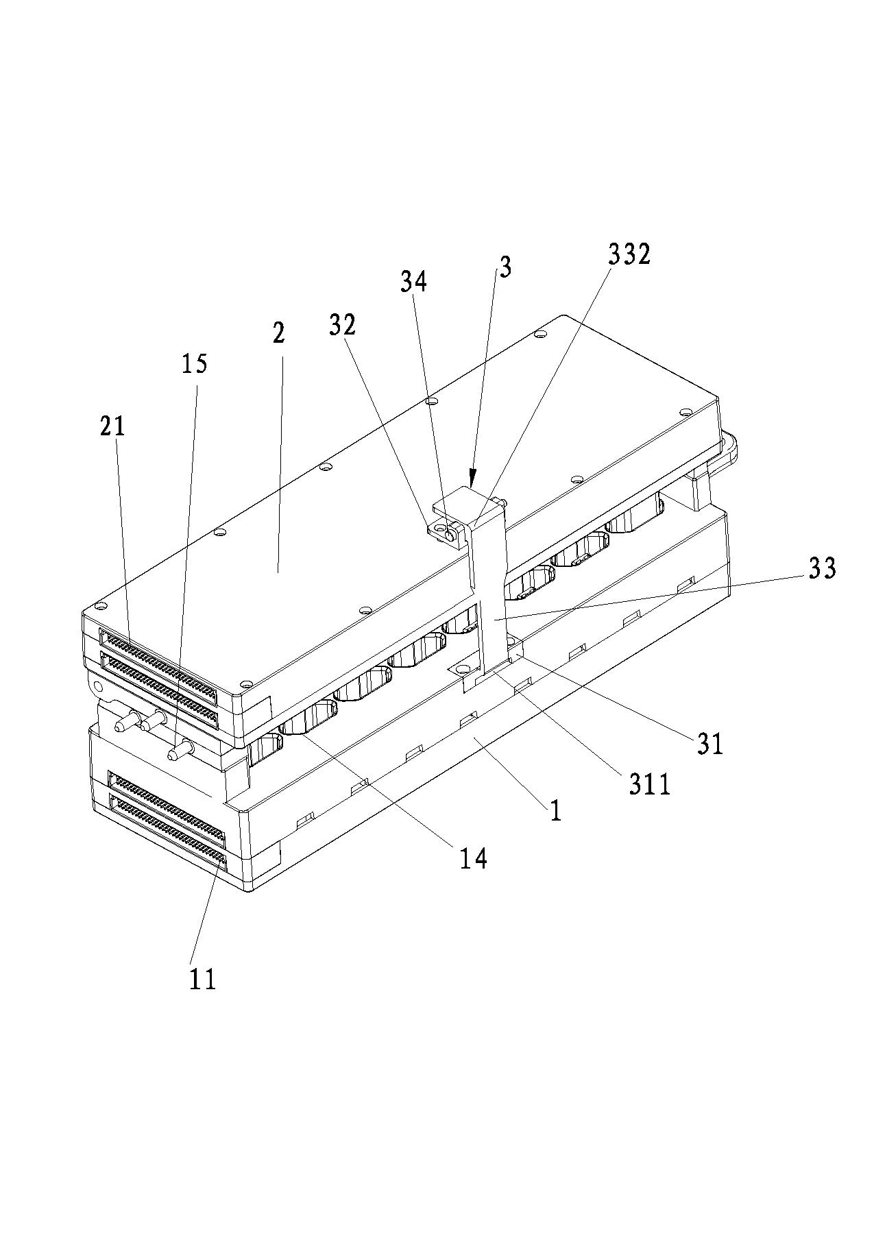
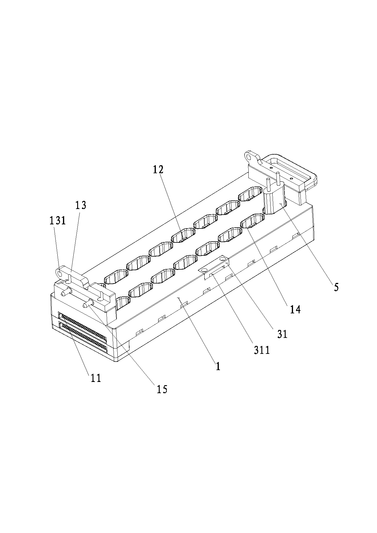
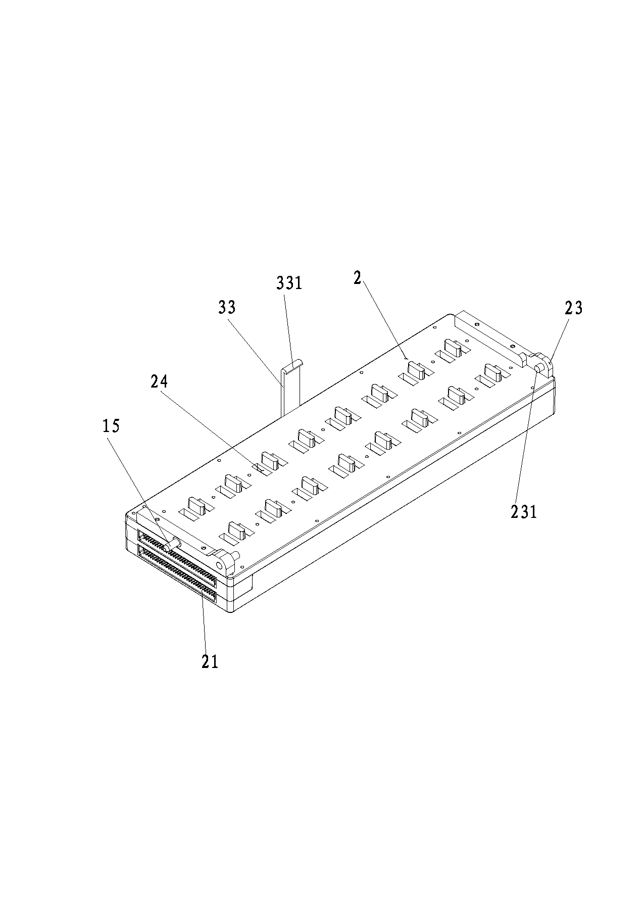
[0039] Embodiment 1 of a kind of aging test jig of the present invention is as Figure 1 to Figure 8 As shown, it includes a base 1 and an upper cover 2 arranged above the base 1, wherein: the base 1 is provided with a base PCB board, the base PCB board is provided with a DC signal connection device 11, and the inner surface of the base 1 opposite to the upper cover 2 is opened There is a product placement slot 14 for placing electronic products 5 . The product placement slot 14 is provided with a DC signal interface 12, and the DC signal interface 12 is electrically connected to the DC signal connection device 11 through the base PCB board; the upper cover 2 is provided with an upper cover PCB board, and the upper cover PCB board is provided with an AC signal connection device 21 and an AC signal interface electrically connected to the AC signal connection device 21 .

[0040] Before the aging test of the electronic product 5, the electronic product 5 is installed in the pro...

Embodiment 2

[0055] A kind of aging test fixture of the present embodiment sees figure 1 and Figure 4 , on the basis of Embodiment 1, the features not explained in this embodiment adopt the explanations in Embodiment 1, and will not be repeated here. The difference between this embodiment and embodiment 1 is:

[0056] The aging test fixture also includes a locking device 3, which is used to lock the upper cover and the base 1 without relative movement when they are closed.

[0057] The locking device 3 includes a first support 31 fixed to the base 1 , a second support 32 fixed to the upper cover 2 , and a locking arm 33 , one end of the locking arm 33 is clamped to the first support 31 , The other end of the locking arm 33 is hinged to the second support 32 .

[0058] Specifically, the locking arm 33 is in an inverted L shape, the bent portion 332 of the locking arm 33 is provided with a hinge shaft 34 , the hinge shaft 34 is hinged to the second support 32 , and the hinge shaft 34 is ...

Embodiment 3

[0063] A kind of aging test fixture of the present embodiment sees figure 1 , Figure 5 to Figure 8 , on the basis of Embodiment 1, the features not explained in this embodiment adopt the explanations in Embodiment 1, and will not be repeated here. The difference between this embodiment and embodiment 1 is:

[0064] refer to Figure 5 , the aging test fixture also includes a load device 4 for providing electronic load required for aging.

[0065] refer to Image 6 , the load device 4 includes a housing 41, a base 42, and a load DC signal connection device 43 and a load AC signal connection device 44 arranged on the base 42, wherein:

[0066] refer to Figure 8 A power supply 421 , a timing board 422 and an electronic load 423 are arranged under the base 42 to provide the power supply and electronic load required for aging.

[0067] refer to Figure 7 The bottom of the housing 41 is provided with a conductive copper plate 411 through which the load device 4 can be energi...


PUM


Abstract

The invention relates to the technical field of ageing tests, particularly relates to a jig for aging tests, and structurally comprises a base and an upper cover arranged above the base. The base is provided with a base printed circuit board (PCB) which is provided with a direct current (DC) signal connecting device, a product placing groove is arranged on the inner surface of the base opposite to the upper cover, and a DC signal interface is arranged in the produce placing groove and electrically connected with the DC signal connecting device through the base PCB. An upper cover PCB is arranged in the upper cover and provided with an alternating current (AC) signal connecting device, and the AC signal connecting device is electrically connected with an AC signal interface. The jig for aging tests has the advantages of being simple in structure, simple and rapid to operate and high in aging testing efficiency, and particularly meets requirements for rapid development of modern enterprises.

Description

technical field [0001] The invention relates to the technical field of aging testing, in particular to an aging testing jig. Background technique [0002] With the development of society, people have higher and higher requirements on the quality of electronic products. In order to improve the quality of electronic products, a series of aging tests need to be carried out on electronic products before leaving the factory. In the prior art, when performing aging tests on electronic products, a single electrical connection test is performed on electronic products, but the efficiency of this single product testing method is very low; on the other hand, during aging tests on electronic products, it is often necessary to For the aging test of multiple items such as light aging and damp heat aging, the interface of the electronic product needs to be electrically connected with different test equipment. Affect the service life of electronic products. [0003] In order to solve the ...

Claims


Application Information

Patent Timeline
Patent Type & Authority Applications(China)
IPC IPC(8): G01R31/00G01R1/04
Inventor 李垂猛刘坚辉邵继铭
Owner DONGGUAN GUANJIA ELECTRONICS EQUIP
Why Eureka
Try Eureka