Uninterrupted power supply (UPS) power box

A power box and chassis technology, which is applied in the direction of electrical components, substation/switch layout details, etc., can solve the problems of inconvenient module installation and difficult module positioning, and achieve convenient daily maintenance, clear and concise wiring, and friendly man-machine interface. Effect

Inactive Publication Date: 2012-07-18
无锡市宇超电气科技有限公司
View PDF5 Cites 4 Cited by
  • Summary
  • Abstract
  • Description
  • Claims
  • Application Information

AI Technical Summary

Problems solved by technology

However, the current UPS cabinets have the problems of inconvenient module installation and difficult module positioning.

Method used


Image

  • Uninterrupted power supply (UPS) power box
  • Uninterrupted power supply (UPS) power box
  • Uninterrupted power supply (UPS) power box

Examples


Embodiment Construction

[0017] The present invention will be further described below in conjunction with the accompanying drawings and embodiments.

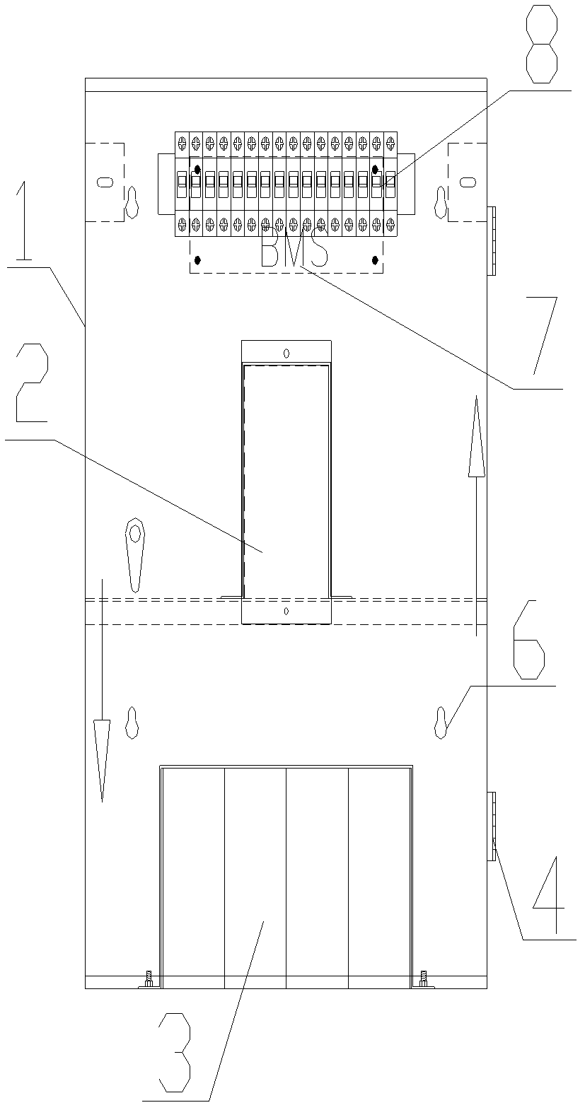
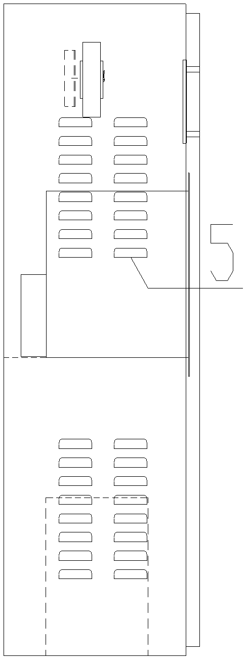
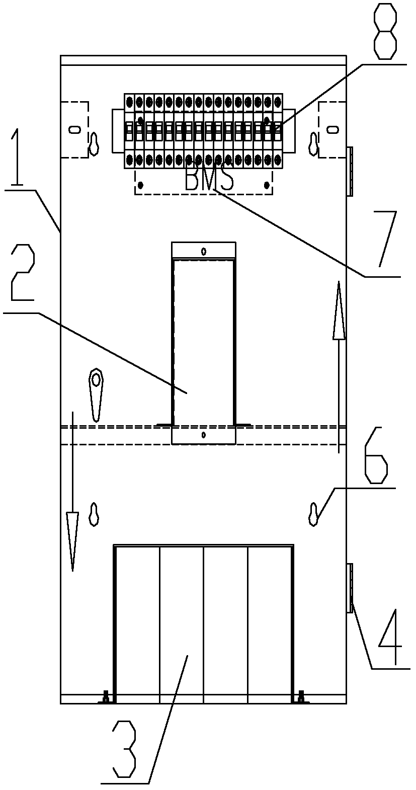
[0018] Such as figure 1 and figure 2 As shown, the UPS power supply box of the present invention includes a cabinet body 1, and the cabinet body 1 is divided into an upper part and a lower part, and a UPS cabinet 2 is provided on the top of the cabinet body 1. The lower part is provided with a lithium battery 3 and a connecting wire terminal 4; a ventilation hole 5 is provided on one side of the cabinet body 1, and a wall-mounted installation hole 6 is provided on the other side, and the opposite side of the wall-mounted installation hole 6 side The side is provided with a BMS interface 7 and a code switch 8; the cabinet 1 is made of cold-rolled steel plate; the lithium battery 3 is a 24V60AH lithium iron phosphate battery; when the UPS power box is used in parallel, the voltage and limit The current value remains consistent; the lithium battery 3 is...


PUM


Abstract

The invention relates to a UPS power box which comprises a cabinet body. The cabinet body comprises an upper portion and a lower portion, a UPS chassis is arranged on the upper portion of the cabinet body, and a lithium battery and a connecting wire terminal are arranged on the lower portion of the cabinet body; a vent hole is arranged on one side surface of the cabinet body, a wall mounting hole is arranged on the other side surface of the cabinet body, and a battery management system (BMS) interface and a dial switch are installed on the side surface opposite to the side surface on which the wall mounting hole is arranged. The UPS power box has the advantages of being convenient to install, small in size, and convenient for daily maintenance.

Description

technical field [0001] The invention relates to a cabinet, in particular to a UPS power cabinet. Background technique [0002] At present, in the field of UPS technology, modular design has become one of the development directions of UPS. The quality of UPS is not only closely related to the circuit design and component quality inside each module, but also directly related to the arrangement and connection of each module. This puts forward higher requirements for the UPS cabinet used to store each module. A reasonable internal layout of the UPS cabinet can provide each module with a better working environment for heat dissipation, ventilation, and safety, and it is also more convenient for daily maintenance. ,maintain. However, the current UPS cabinets have the problems of inconvenient module installation and difficult module positioning. Contents of the invention [0003] Purpose of the invention: The purpose of the invention is to overcome the deficiencies in the prior...

Claims


Application Information

Patent Timeline
Patent Type & Authority Applications(China)
IPC IPC(8): H02B1/46
Inventor 陈杰殷新亮莫俊彪
Owner 无锡市宇超电气科技有限公司
Why Eureka
Try Eureka