Biasing circuit of power amplifier

A power amplifier and bias circuit technology, applied in power amplifiers, improving amplifiers to reduce temperature/power supply voltage changes, etc., can solve the problems of inconvenient adjustment of bias voltage, affecting the performance of power amplifiers, and inability to generate bandgap references. Achieve the effect of suppressing the bias current and meeting the demand

Inactive Publication Date: 2012-07-18
刘轶
View PDF3 Cites 0 Cited by
  • Summary
  • Abstract
  • Description
  • Claims
  • Application Information

AI Technical Summary

Problems solved by technology

When the bias voltage changes from 2.75V to 2.95V, when the temperature changes from -30°C to 80°C, the relative change of the collector current Ic1 caused by the bias current of the RF transistor Q1 will reach 50%; use BandGap bandgap The reference source can better solve the temperature characteristics of the paranoid circuit of the traditional power amplifier, but when the GaAs HBT process is used, the bandgap reference cannot be generated
[0004] To sum up, the performance of the power amplifier has a great relationship with its bias voltage, but the traditional power amplifier bias circuit has the problem that the bias current of the power amplifier changes greatly with the bias voltage and temperature, which affects the performance of the power amplifier. And it is inconvenient to adjust the bias voltage. Therefore, it is necessary to propose improved technical means to solve this problem.

Method used


Image

  • Biasing circuit of power amplifier
  • Biasing circuit of power amplifier
  • Biasing circuit of power amplifier

Examples


Embodiment Construction

[0016] The implementation of the present invention is described below through specific examples and in conjunction with the accompanying drawings, and those skilled in the art can easily understand other advantages and effects of the present invention from the content disclosed in this specification. The present invention can also be implemented or applied through other different specific examples, and various modifications and changes can be made to the details in this specification based on different viewpoints and applications without departing from the spirit of the present invention.

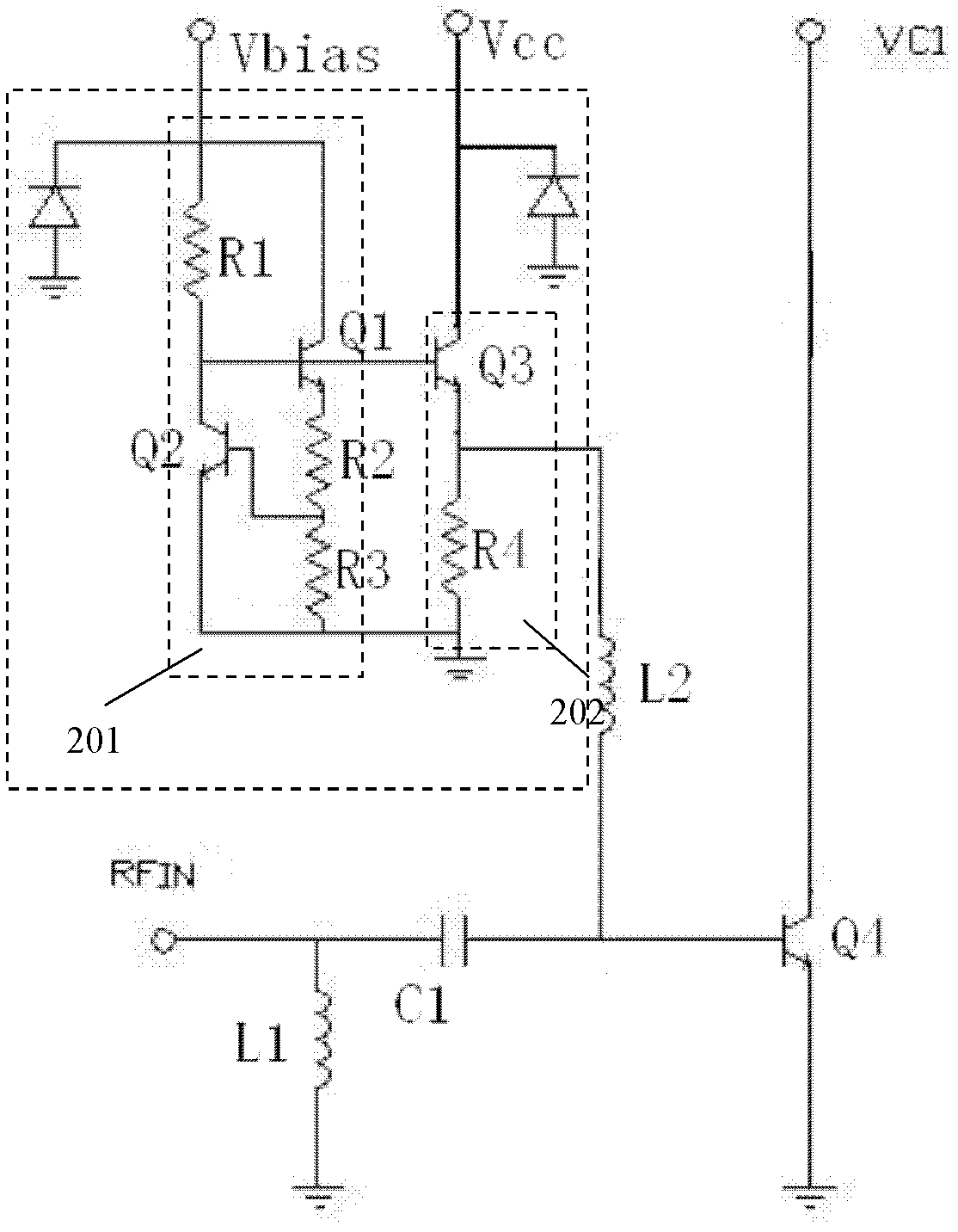
[0017] figure 2 It is a schematic circuit diagram of a preferred embodiment of a power amplifier bias circuit of the present invention. figure 2 The part in the middle dotted line is the bias circuit, which is used to provide a stable bias voltage for the power amplifier, such as figure 2 As shown, a power amplifier bias circuit in the present invention at least includes: a voltage gene...


PUM


Abstract

The invention provides a biasing circuit of a power amplifier. The biasing circuit at least comprises a voltage generating module and a direct current biasing buffer outputting module, wherein the voltage generating module is connected with an external biasing voltage and used for processing the external biasing voltage to output stable voltage output, and the direct current biasing buffer outputting module is connected to an output end of the voltage generating module and used for outputting the stable voltage to the power amplifier through an emitter-follower in a manner of direct current buffer and providing a larger current to the power amplifier. The biasing circuit not only can provide the stable biasing voltage to the power amplifier so as to inhibit the biasing current of the power amplifier from changing greatly with temperature, but also can provide larger biasing current to the power amplifier so as to better meet the requirement of the power amplifier.

Description

technical field [0001] The invention relates to a bias circuit, in particular to a bias circuit of an HBT power amplifier. Background technique [0002] Power amplifiers are widely used in various wireless communication equipment and electronic systems, and their working status is often determined by the bias circuit, so the characteristics of the bias circuit directly affect the performance of the power amplifier, because when the bias current increases with the bias voltage Or when the temperature changes, the working state of the power amplifier will also change accordingly, so the performance of the power amplifier will also change accordingly, especially at low temperature and low pressure, the deterioration of the performance of the power amplifier caused by the bias circuit is particularly obvious. Therefore, a bias circuit with a bias voltage capable of compensating for temperature changes is needed to provide bias to the power amplifier, so as to ensure that the pow...

Claims


Application Information

Patent Timeline
Patent Type & Authority Applications(China)
IPC IPC(8): H03F3/20H03F1/30
Inventor 刘轶
Owner 刘轶
Why Eureka
Try Eureka