
Power source device with adjustable gears for LED (Light Emitting Diode)

A power supply device and gear position technology, which is applied in the direction of electric light source, lighting device, lamp circuit layout, etc., can solve the problems that the two power sources cannot be mixed with each other, there is no setting for online power adjustment, and the power supply cannot be used, etc., so as to achieve a simple structure , increase brightness, save cost effect

Active Publication Date: 2014-09-03
江苏山水节能服务股份有限公司
View PDF3 Cites 0 Cited by
  • Summary
  • Abstract
  • Description
  • Claims
  • Application Information

AI Technical Summary

Problems solved by technology

[0002] At present, among the LED constant current drive power supplies, none of them have a device to adjust the power online. The existing LED constant current power supplies are all paired with the same type of lamp tubes to adjust the current, and different batches of products can be used. The use of power supply for LED lamps has certain limitations, especially in the process of mass production. For example: there are 12W lamps and 14W lamps. The traditional LED power supply must carry out the current according to these two lamps. Matching, the two power supplies cannot be mixed with each other during use, that is to say, one power supply cannot be used on two kinds of lamp tubes. If you want to use it, you must re-adjust the parameters and data, which is very inconvenient to use.
[0003] In places where large supermarkets use electricity for a long time, after the LED lights have been used for a long time, the light tubes will have a certain amount of light decay, which is troublesome to replace and wasteful cost

Method used


Image

  • Power source device with adjustable gears for LED (Light Emitting Diode)

Examples


Embodiment Construction

[0013] The preferred embodiments of the present invention will be described in detail below in conjunction with the accompanying drawings, so that the advantages and features of the present invention can be more easily understood by those skilled in the art, so as to define the protection scope of the present invention more clearly.

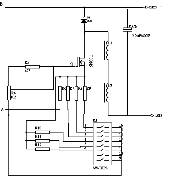
[0014] see figure 1 , the embodiment of the present invention includes:

[0015] An LED gear-adjustable power supply device, comprising a field effect transistor Q1, an access switch K1, a seventh resistor R7, an eighth resistor R8, a ninth resistor R9, a tenth resistor R10, an eleventh resistor R11, and a twelfth resistor R12, a first inductor L1, a second inductor L2, a capacitor C6, and a diode. The source of the field effect transistor Q1 is connected to the resistor R7-R12, and the other ends of R7-R12 are respectively connected to the access switch Q1, and the other end of the access switch is connected to the input port A. The gate of Q1 ...


PUM


Abstract

The invention discloses a power source device with adjustable gears for an LED (Light Emitting Diode). The power source device comprises a field-effect tube, a path switch and multiple resistances, wherein a source electrode of the field-effect tube is connected with the multiple resistances; the other ends of the multiple resistances are respectively connected with the path switch; the other end of the path switch is connected with a first input port; a grid of the field-effect tube is connected with a first input end through a grid resistance, and a drain of the field-effect tube is connected with a positive electrode of a diode; a negative electrode of the diode is connected with a second input end; and the size of the power is changed by changing the make-and-break of the path switch. According to the mode, the driving mode of matching the current single power source with a single lamp tube can be changed; the power source device has simple structure and is wider in the application range; the production cost is invisibly reduced; one power source can be applied to LED lamp tubes of 8W-20W; the power source device is more convenient to use; the luminance of the light decayed lamp tube can be increased by secondly adjusting the power of the power source very well; and the cost of lamp tube replacement is saved.

Description

technical field [0001] The invention relates to a power supply device, in particular to a power supply device with adjustable LED stalls. Background technique [0002] At present, among the LED constant current drive power supplies, none of them have a device to adjust the power online. The existing LED constant current power supplies are all paired with the same type of lamp tubes to adjust the current, and different batches of products can be used. The use of power supply for LED lamps has certain limitations, especially in the process of mass production. For example: there are 12W lamps and 14W lamps. The traditional LED power supply must carry out the current according to these two lamps. Matching, the two power supplies cannot be mixed with each other during use, that is to say, one power supply cannot be used on two kinds of lamp tubes. If you want to use it, you must re-adjust the parameters and data, which is very inconvenient to use. [0003] In places where large...

Claims


Application Information

Patent Timeline
Patent Type & Authority Patents(China)
IPC IPC(8): H05B37/02
Inventor 胡春平
Owner 江苏山水节能服务股份有限公司
Learn More