Display device, unevenness correction method, and computer program

A technology for displaying equipment and uniformity, applied to static indicators, instruments, electrical components, etc., can solve problems such as unevenness, uneven lighting, uneven irradiation of laser beams, etc., to prevent power consumption and prevent circuit area from increasing Effect

Inactive Publication Date: 2012-07-18
SONY CORP
View PDF5 Cites 4 Cited by
  • Summary
  • Abstract
  • Description
  • Claims
  • Application Information

AI Technical Summary

Problems solved by technology

[0007] However, since the laser beam is expanded into a fan shape, the laser beam may not be uniformly irradiated onto the panel
Therefore, the fabricated panel tends to have muscle-like unevenness in light emission along the horizontal or vertical direction
Illumination unevenness may locally occur in other than horizontal or vertical directions
In addition, the thickness and characteristics of TFT, the impedance of various wirings, etc. show dispersion due to the influence of air temperature, humidity and environment, manufacturing dispersion from manufacturing installation, etc., and thus it appears to be uneven

Method used


Image

  • Display device, unevenness correction method, and computer program
  • Display device, unevenness correction method, and computer program
  • Display device, unevenness correction method, and computer program

Examples


no. 1 example

[0038] [1-1. Display device configuration]

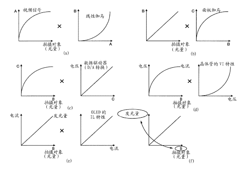
[0039][1-2 Characteristics of a signal flowing through a display device]

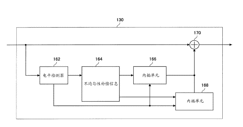
[0040] [1-3 Configuration of Nonuniformity Compensation Unit]

no. 2 example

[0042]

[0043]

[0044] [1-1. Display device configuration]

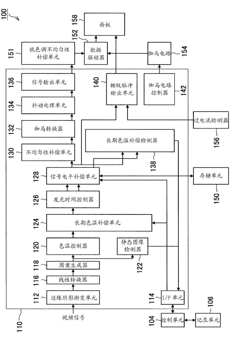
[0045] First, the configuration of the display device according to the first embodiment of the present invention will be explained. figure 1 is an explanatory diagram illustrating the configuration of the display device 100 according to the first embodiment of the present invention. Hereinafter, use figure 1 The configuration of the display device 100 applied to the first embodiment of the present invention is explained.

[0046] Such as figure 1 As shown, the display device 100 according to the embodiment of the present invention is configured to include a control unit 104, a recording unit 106, a signal processing integrated circuit 110, a storage unit 150, a low tone non-uniformity compensation unit 151, a data driver 152, a gamma circuit 154 , overcurrent detector 156 and panel 158 .

[0047] The signal processing integrated circuit 110 is configured to include an edge shading-off unit (shading-off) 112...


PUM


Abstract

Disclosed is a display device that can both correct unevenness in a linear space and set one unevenness-correction plane outside the linear space, correcting unevenness in ultra-low-brightness regions, thereby effectively correcting unevenness in ultra-low-brightness regions while minimizing increases in power consumption and circuit size. The disclosed display device is provided with: pixels provided with light-emitting elements, which emit light according to levels of current, and pixel circuits that control currents applied to said light-emitting elements in accordance with a video signal; a display unit in which scan lines, which with a prescribed scan period supply the pixels with a selection signal that selects the pixels to be turned on, and data lines, which supply the aforementioned video signal to the pixels, are arranged in a matrix; a first unevenness-correction unit which corrects brightness unevenness in video signals with linear characteristics; and a second unevenness-correction unit which corrects brightness unevenness in video signals with gamma characteristics, in prescribed regions and those below.

Description

technical field [0001] The present invention relates to a display device, a nonuniformity compensation method, and a computer program, and more particularly, to an active matrix type display device in which scanning lines, data lines, and pixel circuits are arranged in a matrix, and the scanning lines are arranged in a matrix. A pixel is selected in a predetermined scan period, the data line gives brightness information for driving the pixel, and the pixel circuit causes the light emitting device to emit light depending on the amount of current. Background technique [0002] As flat and thin display devices, liquid crystal displays and plasma displays using liquid crystals are now practically used. [0003] A liquid crystal display is a display that has a backlight and displays an image by passing or cutting off light from the backlight by changing the arrangement of liquid crystal elements by applying a voltage. In addition, a plasma display is a display device that become...

Claims


Application Information

Patent Timeline
Patent Type & Authority Applications(China)
IPC IPC(8): G09G3/30G09G3/20H01L51/50
CPCG09G3/20G09G2330/04G09G2320/0673G09G2320/0666G09G2320/0276G09G3/2092G09G3/30
Inventor 森秀人
Owner SONY CORP
Why Eureka
Try Eureka