
Exhaust pipe automatic cleaning device and glue developing machine

An exhaust duct, automatic cleaning technology, applied in the direction of cleaning hollow objects, cleaning methods and utensils, photoengraving process coating equipment, etc. Manpower, the effect of reducing downtime

Active Publication Date: 2016-09-28
SHANGHAI HUAHONG GRACE SEMICON MFG CORP
View PDF5 Cites 0 Cited by
  • Summary
  • Abstract
  • Description
  • Claims
  • Application Information

AI Technical Summary

Problems solved by technology

[0005] The purpose of the present invention is to provide an automatic cleaning device for exhaust pipes and a glue-coating and developing machine to solve the cumbersome problem of dismantling and cleaning the existing exhaust pipes

Method used


Image

  • Exhaust pipe automatic cleaning device and glue developing machine
  • Exhaust pipe automatic cleaning device and glue developing machine

Examples


Embodiment Construction

[0018] In order to make the above objects, features and advantages of the present invention more comprehensible, specific implementations of the present invention will be described in detail below in conjunction with the accompanying drawings.

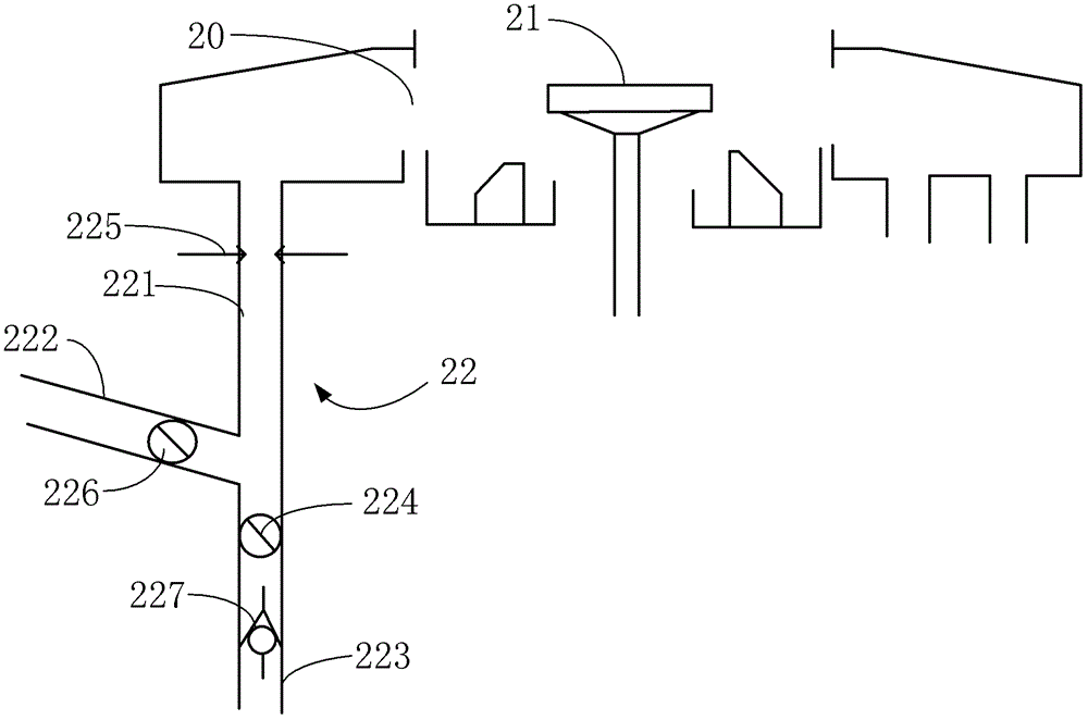
[0019] see figure 2 , figure 2 Shown is a schematic structural view of the exhaust pipe automatic cleaning device and the gumming and developing machine of the present invention. Depend on figure 2 It can be seen that the gluing and developing machine platform provided in this embodiment includes a gluing chamber 20, a wafer carrier 21, an exhaust duct 22, and an exhaust duct automatic cleaning device arranged on the exhaust duct 22. The wafer carrier table 21 is located at the central position of the gluing chamber 20, the wafer is placed on the wafer carrier table 21, the exhaust pipe 22 is arranged at the bottom of the gluing chamber 20, and It communicates with the gluing chamber 20 .

[0020] read on figure 2 , the automa...


PUM

PropertyMeasurementUnit
angleaaaaaaaaaa

Abstract

The present invention relates to the field of semiconductor lithography, and provides an automatic cleaning device for an exhaust pipe, which is installed in the exhaust pipe of a glue-coating and developing machine. pipe, the first pipe communicates with the gluing chamber of the gluing developing machine, and the exhaust pipe automatic cleaning device includes a nozzle and a liquid discharge pipe connected to an external cleaning solvent source, the nozzle is arranged on the inner wall of the first pipe, and the liquid discharge pipe It is connected under the first pipe and communicated with the first pipe. The present invention also provides a glue-coating developing machine, comprising a wafer carrier set in the glue-coating chamber and an exhaust pipe communicating with the glue-coating chamber, the exhaust pipe is provided with the above-mentioned exhaust pipe. Air pipe automatic cleaning device. Through the nozzle, the cleaning solvent can be sprayed to the first pipe of the exhaust pipe, which is easy to accumulate photoresist dust particles, so as to achieve the purpose of timely cleaning the photoresist dust particles accumulated on the inner wall of the exhaust pipe without dismantling and washing the exhaust pipe.

Description

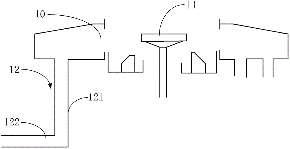
technical field [0001] The invention relates to the field of semiconductor photolithography, in particular to an automatic cleaning device for an exhaust pipe and a glue-coating and developing machine. Background technique [0002] The rubber coating and developing machine in the process of semiconductor lithography, its structure is as follows figure 1 As shown, it includes a gluing chamber 10, a wafer carrier 11 and an exhaust duct 12, the wafer carrier 11 is arranged inside the gluing chamber 10, and a wafer is placed on the wafer carrier 11, at present, the exhaust pipe 12 is an elbow composed of a vertical pipe 121 and a horizontal pipe 122 connected to each other, and the vertical pipe 121 communicates with the glue chamber 10 for Discharge the gas in the gluing chamber. During the gluing process, the gluing and developing machine uses a high-speed rotating motor to drive the wafer carrier 11 to rotate. During this process, about 80% of the photoresist will be thrown ...

Claims


Application Information

Patent Timeline
Patent Type & Authority Patents(China)
IPC IPC(8): B08B9/032G03F7/16
Inventor 凌意明周孟兴江瑞星王逸尔
Owner SHANGHAI HUAHONG GRACE SEMICON MFG CORP
Learn More