
Pier thickness stamping process of separated pull ring and pier thickness stamping die

A technology for separating pull rings and stamping dies, applied in forming tools, manufacturing tools, metal processing equipment, etc., can solve the problems of reduced wall thickness at the window of the separation pull ring, failure to meet the use strength requirements, and unusable clutch assembly, etc. Achieve the effects of increasing strength, strong practicability, and reducing deviations in shape and size

Inactive Publication Date: 2012-07-25
SINO TRUK JINAN POWER
View PDF5 Cites 6 Cited by
  • Summary
  • Abstract
  • Description
  • Claims
  • Application Information

AI Technical Summary

Problems solved by technology

[0003] In the manufacturing process of the diaphragm clutch separation pull ring, the wall thickness of the material is reduced after stamping and stretching. In order to ensure the wall thickness requirements of the product, due to the limitation of the stamping process, the dimensional deviation after stamping is relatively large, and the subsequent turning processing of some workpieces has no There is enough margin to turn the entire processing surface up, and the separation pull ring with this defect is unevenly stressed during use and is easy to crack and break at the side window, making the entire clutch assembly unusable
Under the condition of cutting allowance that the entire surface can be machined, the wall thickness at the window of the separation ring is reduced and cannot meet the service strength requirements

Method used


Image

  • Pier thickness stamping process of separated pull ring and pier thickness stamping die
  • Pier thickness stamping process of separated pull ring and pier thickness stamping die
  • Pier thickness stamping process of separated pull ring and pier thickness stamping die

Examples


Embodiment Construction

[0024] The present invention will be further elaborated below through specific examples. It should be noted that the following descriptions are only for explaining the present invention, and do not limit its content.

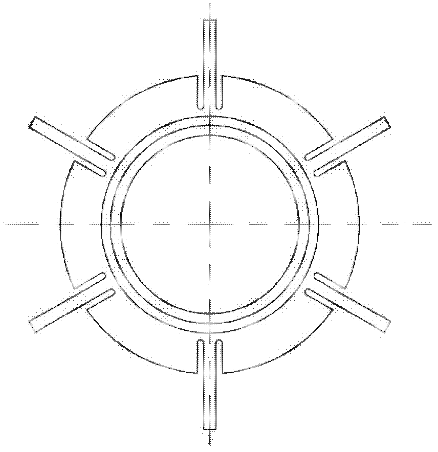
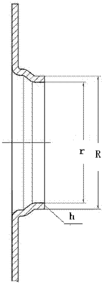
[0025] A pier thickness stamping process for separating the pull ring, such as figure 2 As shown, the wall thickness of the separated pull ring product is 4.5mm, and the inner hole size is 89mm. This process needs to be carried out after stretching and forming. The process is: after stamping and stretching the separation ring of the diaphragm clutch, it is subjected to a pier thickness trimming stamping process. The stamping process for trimming the pier thickness is:

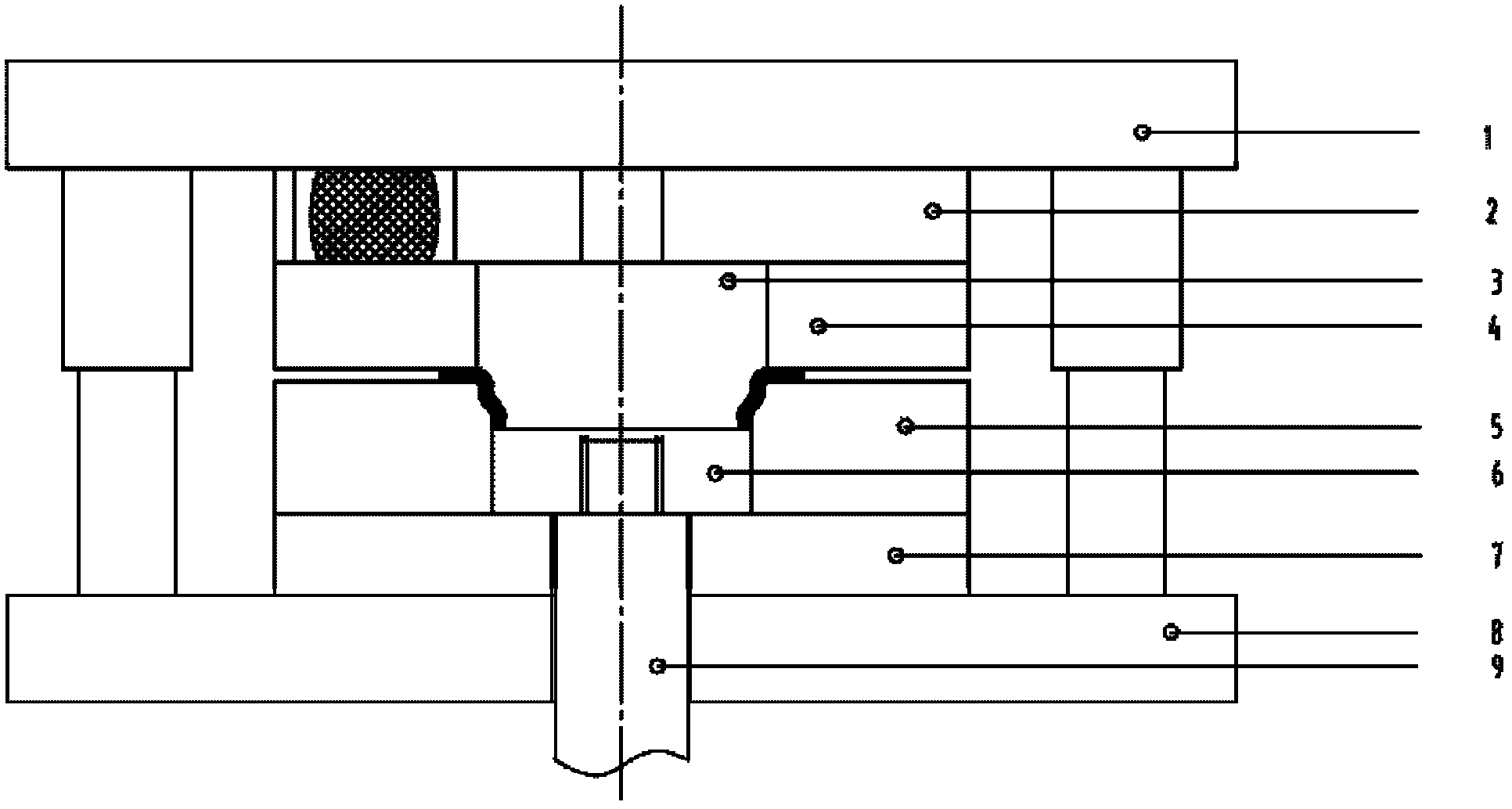
[0026] (1) Select the designed pier thickness trimming stamping die (such as figure 1 As shown): the mold includes an upper mold base, a lower mold base and a lower ejector rod. The ejector rod passes through the lower top seat and the lower backing plate to connect with the lower top plate; ...


PUM

PropertyMeasurementUnit
Wall thicknessaaaaaaaaaa

Abstract

The invention discloses a pier thickness stamping process of a separated pull ring and a pier thickness stamping die. The process disclosed by the invention is characterized in that: a pier thickness finishing and stamping process is further added after stamping and stretch forming the separated pull ring of a membrane clutch, wherein the added process increases wall thickness of a part to be processed and finishes the stretch formed workpiece so as to reduce the shape and dimensional deviation. The die comprises an upper die base, a lower die base and a lower mandrill. The upper die is prepared by reserving turning allowance of 0.5mm according to inner hole dimension of a product and the lower die is prepared by a gap between the upper die and the lower die that is the wall thickness of the product plus the turning allowance of 0.5mm reserved by the upper die. The die provided by the invention is designed by tightly combining dimension of the separated pull ring to be processed and the turning allowance, and a structure and parameters represent the creative labor. The separated pull ring processed by the process and die provided by the invention not only increases the strength of an easily damaged part of the processed separated pull ring, but also finishes the stretch formed workpiece so as to reduce the shape and dimensional deviation. Design idea of the invention can be further applied to other thin wall pieces.

Description

[0001] technical field [0002] The invention relates to a pier thickness stamping process and a pier thickness stamping die for separating a pull ring. Background technique [0003] In the manufacturing process of the diaphragm clutch separation pull ring, the wall thickness of the material is reduced after stamping and stretching. In order to ensure the wall thickness requirements of the product, due to the limitation of the stamping process, the dimensional deviation after stamping is relatively large, and the subsequent turning processing of some workpieces has no There is enough margin to turn the entire processing surface up, and the separation pull ring installed with this defect will be easily cracked and broken at the side window due to uneven force during use, making the entire clutch assembly unusable. Under the condition of cutting allowance that the entire surface can be machined, the wall thickness at the window of the separation ring is reduced and cannot meet...

Claims


Application Information

Patent Timeline
IPC IPC(8): B21D22/06B21D37/10B21D53/16
Inventor 任进丽张勇杨红宇姚志刚
Owner SINO TRUK JINAN POWER
Learn More