Hot melting device and hot melting method thereof

A hot-melting machine and hot-melting technology, applied in the field of hot-melting machines, can solve the problems of many melting point burrs and waste of energy, and achieve the effects of obvious energy saving, long service life and low welding temperature.

Inactive Publication Date: 2012-07-25
太仓市皓荣化工科技有限公司
View PDF8 Cites 22 Cited by
  • Summary
  • Abstract
  • Description
  • Claims
  • Application Information

AI Technical Summary

Problems solved by technology

[0003] Purpose of the invention: The purpose of the present invention is to provide a hot-melt machine to solve the problems of energy waste of traditional hot-melt machines, many burrs at the melting point after bonding and generation of toxic gas. At the same time, the invention provides a hot-melt method for the hot-melt machine

Method used


Image

  • Hot melting device and hot melting method thereof
  • Hot melting device and hot melting method thereof

Examples


Embodiment Construction

[0021] Below in conjunction with accompanying drawing, the present invention is further described in detail:

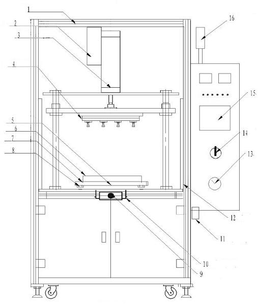
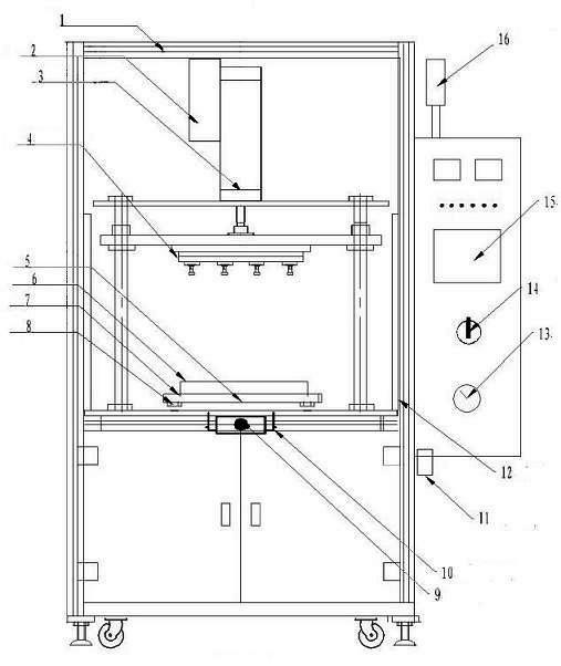
[0022] The invention relates to a hot-melt machine with a new structure, which includes a cabinet, wheels and fixed feet are arranged at the bottom of the cabinet, which is convenient for the handling and fixing of the machine, and a frame 1 is arranged on the upper side of the cabinet, and the top surface of the cabinet A pair of linear guide rails 8 are set, and a mobile workbench 7 is arranged on the linear guide rails 8. In this way, the mobile workbench 7 can move forward and backward along the linear guide rail 8, and a clamp 6 is set on the mobile workbench 7. . On the upper part of the frame 1, set a moving cylinder 3 up and down, one end of the moving cylinder 3 is connected to the frame 1, and the other end is connected to the hot mold 4, the hot mold 4 is a rectangular flat plate, and several components are arranged on the lower side of the flat plate. Typ...


PUM


Abstract

The invention relates to a hot melting device which comprises a stander and a cabinet, wherein the stander is arranged at the upper side of the cabinet, the side face of the stander is provided with a control box, the top surface of the cabinet is provided with a movable work table and a mould heating mould, the mould heating mould is fixedly connected with the top end of the stander by an upward / downward moving air cylinder, the mould heating mould is guided by stand columns arranged at two sides of the mould heating mould, the upper side of the movable work table is provided with a clamp, and the lower side of the movable work table is provided with a guide rail which moves the movable work table front and back and an air cylinder required for offering a frontward / backward motion. The hot melting device further comprises a pressurizing air cylinder, wherein the pressurizing air cylinder is arranged on the upward / downward moving air cylinder. Meanwhile, the invention further discloses a hot melting method of the hot melting device. Workpieces are connected with one another in a pressurizing way by means of hot melting, and a welding pressure is changed in the process of welding. Compared with the conventional hot melting welding mode, the pressure-variable welding mode is low in welding temperature, smooth in welding points, free from volatile smell during the conventional high-temperature hot melting welding of the plastic, and obvious in energy-saving effect, and the welding head and heating parts are long in service life.

Description

technical field [0001] The invention relates to a hot-melt machine, in particular to a hot-melt machine which reduces the hot-melt temperature under the premise of ensuring the hot-melt effect. At the same time, the invention discloses a hot-melt method thereof. Background technique [0002] In industrial production, the bonding between plastic parts is generally carried out by using a hot melt machine. Specifically, a hot melt machine is used to melt the heated melting point of the workpiece so that it can be combined with another workpiece. The traditional hot-melt machine only uses heat to melt the melting point to generate adhesive force, and melting at the melting point will produce a large amount of harmful volatile gases, which will cause harm to the human body, and the melting point after bonding will have burrs, which require post-processing. It also wastes energy. Contents of the invention [0003] Purpose of the invention: The purpose of the present invention i...

Claims


Application Information

Patent Timeline
Patent Type & Authority Applications(China)
IPC IPC(8): B29C65/40
Inventor 陆勇
Owner 太仓市皓荣化工科技有限公司
Why Eureka
Try Eureka