Sundries removing machine used for belt conveyer

A sundry machine and belt conveyor technology, applied in the direction of conveyor objects, conveyors, transportation and packaging, etc., can solve the problems of long installation time, difficult maintenance, system blockage, etc., achieve high degree of automation, low investment cost, The effect of easy maintenance

Inactive Publication Date: 2012-07-25
BEIJING HAOHUA YUANHANG ENG TECH
View PDF8 Cites 4 Cited by
  • Summary
  • Abstract
  • Description
  • Claims
  • Application Information

AI Technical Summary

Problems solved by technology

[0002] At present, when industries such as power generation, iron and steel, coal mining, and coking use belts to transport materials, a head-rotating tooth-shaped debris removal device is generally installed at the head of the belt. It mainly has the following disadvantages: 1. The head-rotating tooth-shaped debris removal device It is installed under the falling material. When the material falls, it has a greater impact on the hook teeth. The corresponding hook teeth have larger specifications. About 5 times; 2. Because the falling material has a greater impact on the hook teeth, on the one hand, the hook teeth are easily deformed, causing collisions between teeth, and on the other hand, the wear of the hook teeth will be accelerated; 3. Due to the falling The material has a greater impact on the hook teeth, so the power of the drive motor is relatively large, and the investment cost is much higher than that of the debris removal machine used for belt conveyors. In addition, the power of the drive motor increases, and the power consumption per unit time increases. , increase the operating cost of the equipment; 4. The installation of the head rotating tooth-shaped debris removal device needs to be shut down for installation, and the workload is large. On the one hand, the transformation cost is high. On the other hand, a long installation time will affect on-site production and difficult maintenance ;5. The material is thrown down by the head roller, and the material flow is dispersed after passing through the hook teeth. The dispersed material is scattered on the discharge funnel, which is easy to form accumulated material, and finally causes the system to block the material

Method used


Image

  • Sundries removing machine used for belt conveyer
  • Sundries removing machine used for belt conveyer
  • Sundries removing machine used for belt conveyer

Examples


Embodiment Construction

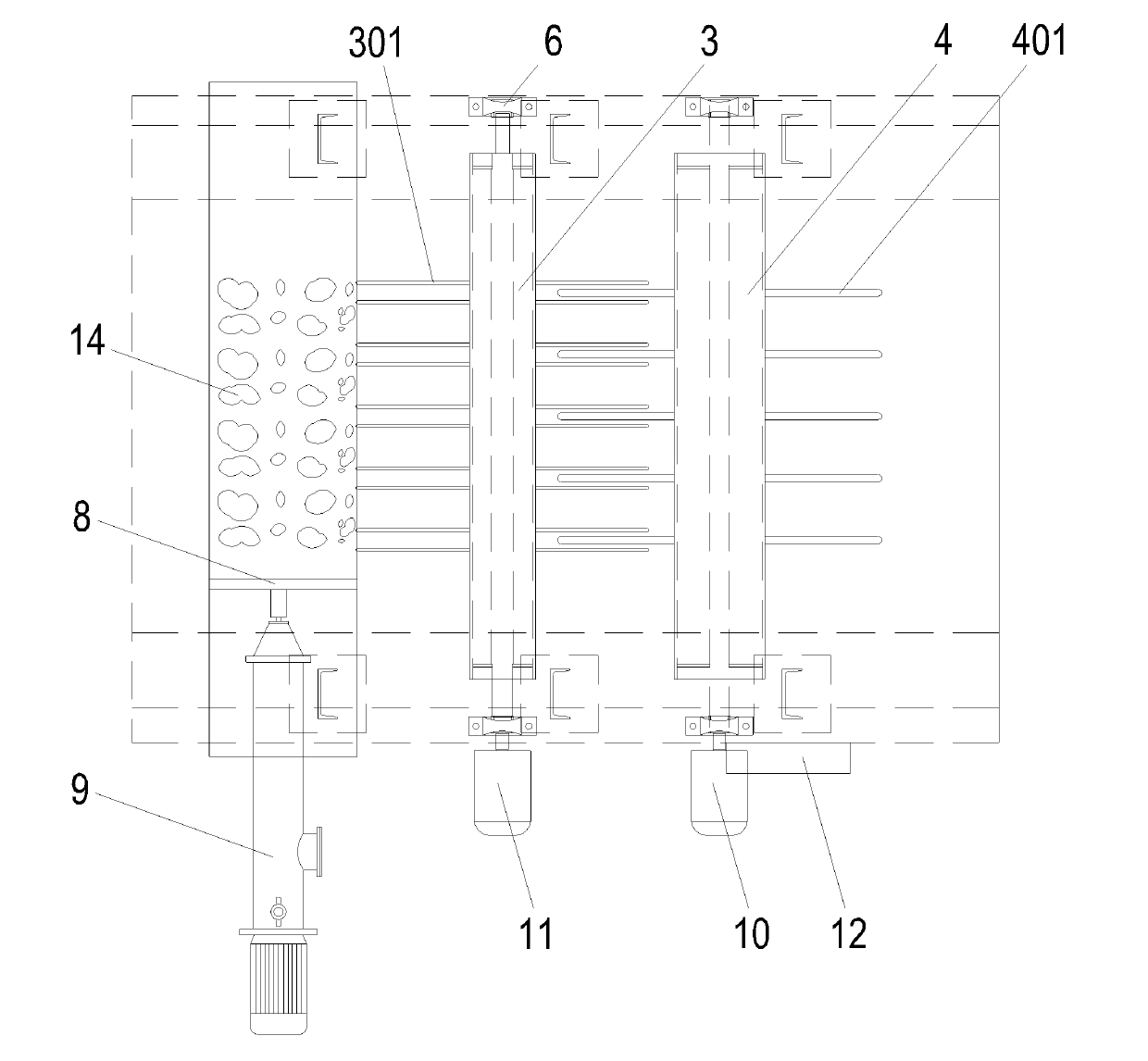
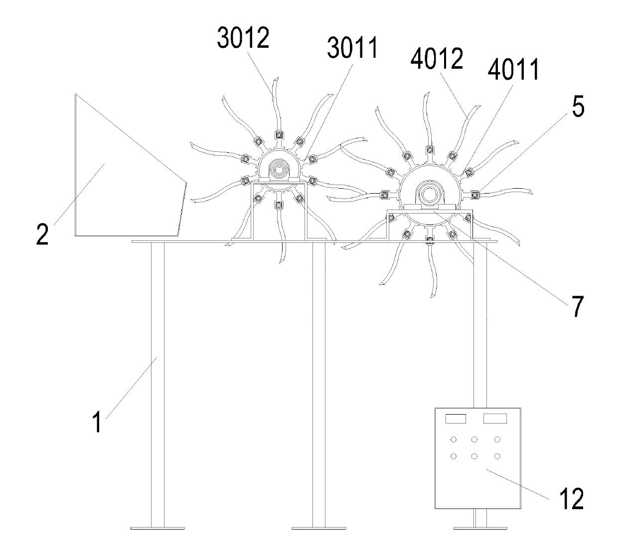
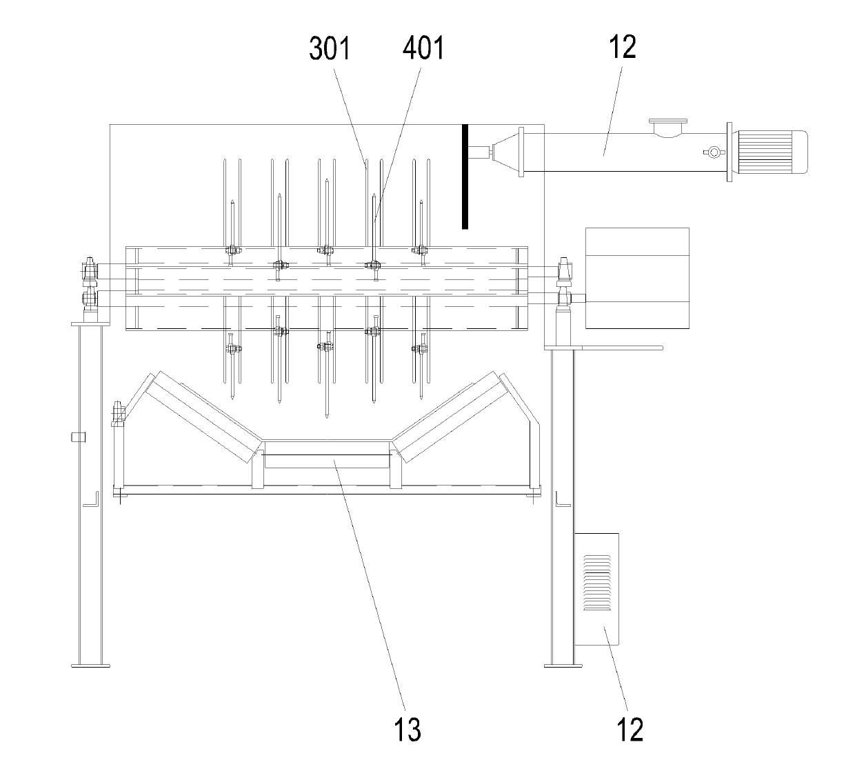
[0020] Such as Figure 1-3 As shown, a kind of debris removal machine for belt conveyors according to the embodiment of the present invention includes a frame 1, and the top of the frame 1 is sequentially provided with a glove box 2 and a debris removal device 3 from left to right And getting the sundries device 4, dialing the sundries device 3 and getting the sundries device 4 are interlaced with each other, and dialing the sundries device 3 and getting the sundries device 4 are respectively connected with the drive system.

[0021] The sundries-taking device 4 is provided with a plurality of hook teeth 401, the hook teeth include a hook tooth seat 4011 and a hook tooth tip 4012, and the hook tooth seat 4011 is connected with the hook tooth tip 4012 by a bolt 5; The bearing 6 and the bearing seat plate 7 are arranged on the frame 1, and the debris removal device 4 is connected with the first motor reducer in the drive system through a shaft coupling.

[0022] The sundry sett...


PUM


Abstract

The invention relates to a sundries removing machine used for a belt conveyer. The sundries removing machine comprises a rack, wherein a sundries box, a sundries stirring device and a sundries taking device are arranged at the top of the rack from the left to the right, the sundries stirring device and the sundries taking device are staggered from each other and are respectively connected with a driving system; the sundries taking device is provided with a plurality of hook teeth and is arranged on the rack by a mounted bearing and a bearing seat plate, and the sundries taking device is connected with a first motor reducing gear in the driving system by a coupling; a plurality of stirring teeth are arranged on the sundries stirring device, one hook tooth is staggered between each pair of stirring teeth; and the sundries stirring device is arranged on the rack by the mounted bearing and the bearing seat plate and is connected with a second motor reducing gear in the driving system by a coupling. The sundries removing machine has the beneficial effects that the structure is simple, the installation, the use and the maintenance are convenient, the investment is low, and the degree of automation is high.

Description

technical field [0001] The invention relates to an impurity remover for a belt conveyor. Background technique [0002] At present, when the power generation, steel, coal mine, coking and other industries use the belt to transport materials, the head rotating tooth-shaped debris removal device is generally installed at the head of the belt, which mainly has the following disadvantages: 1. The head rotating tooth-shaped debris removal device It is installed under the falling material. When the material falls, it has a greater impact on the hook teeth. The corresponding hook teeth have larger specifications. About 5 times; 2. Because the falling material has a greater impact on the hook teeth, on the one hand, the hook teeth are easily deformed, causing collisions between teeth, and on the other hand, the wear of the hook teeth will be accelerated; 3. Due to the falling The material has a greater impact on the hook teeth, so the power of the driving motor is relatively large, ...

Claims


Application Information

Patent Timeline
Patent Type & Authority Applications(China)
IPC IPC(8): B65G47/00B65G15/00
Inventor 谢建伟
Owner BEIJING HAOHUA YUANHANG ENG TECH
Why Eureka
Try Eureka