
Coagulating sedimentation device

A technology of coagulation, sedimentation and coagulation, which is applied in the direction of flocculation/sedimentation water/sewage treatment, etc., can solve the problems of easy damage of the agitator, troublesome equipment maintenance, and difficult maintenance, so as to reduce costs, reduce maintenance costs, and facilitate maintenance Effect

Inactive Publication Date: 2012-07-25
SUZHOU QINGHEFANG ENVIRONMENTAL PROTECTION TECH
View PDF8 Cites 4 Cited by
  • Summary
  • Abstract
  • Description
  • Claims
  • Application Information

AI Technical Summary

Problems solved by technology

The use of flocculation mixing equipment consumes more electric energy, and the agitator is also easily damaged and difficult to maintain, which brings trouble to equipment maintenance

Method used


Image

  • Coagulating sedimentation device
  • Coagulating sedimentation device
  • Coagulating sedimentation device

Examples


Embodiment 1

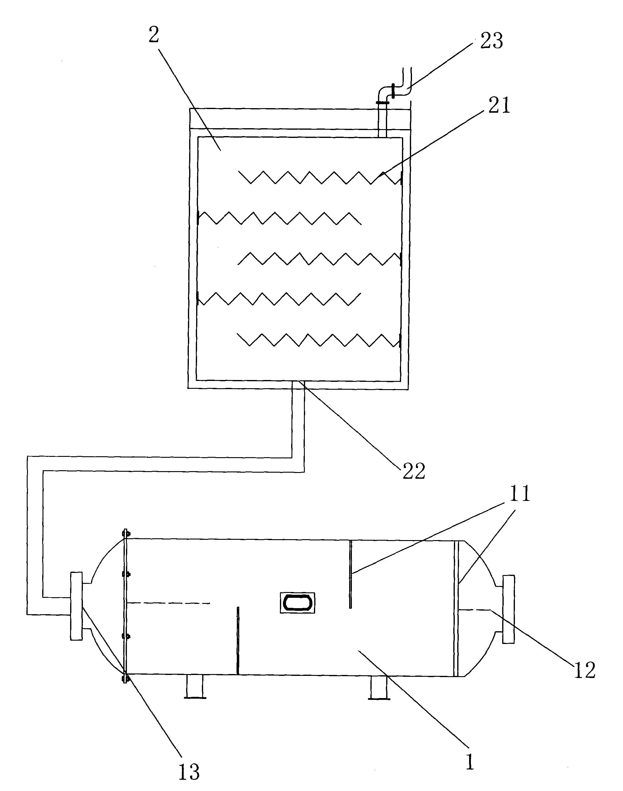
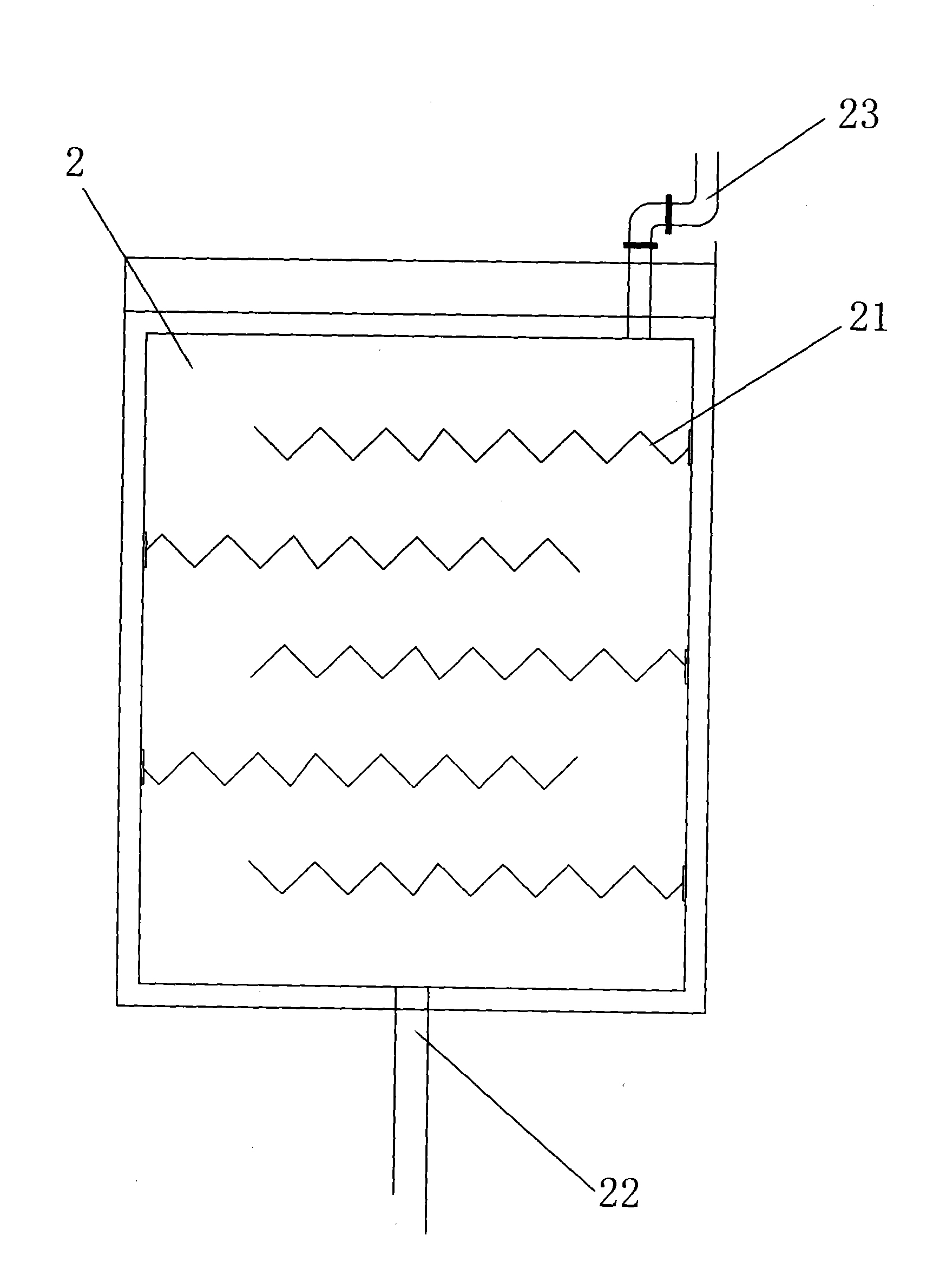
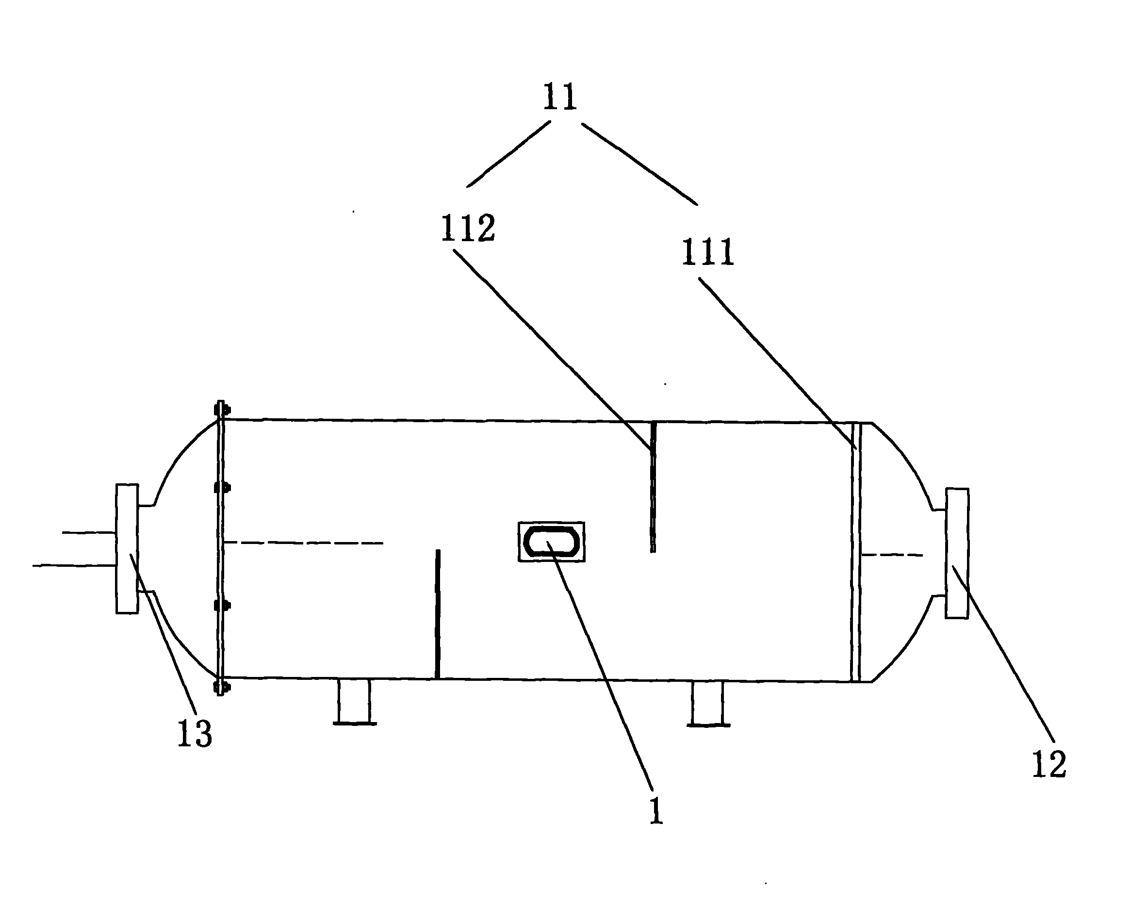
[0026] Such as figure 1 ,Such as figure 2 ,Such as image 3 and as Figure 4 As shown, a coagulation sedimentation equipment includes a mixing reactor 1 and a coagulation reaction tank 2, the mixing reactor 1 is connected to the coagulation reaction tank 2 through pipelines, and the mixing reactor 1 includes First inlet 12 and first outlet 13, described coagulation reaction tank 2 comprises second inlet 22 and second outlet 23, described first outlet 13 links to each other with described second inlet 22, described coagulation reaction tank 1 There are baffles 21 for blocking water flow, the baffles 21 are corrugated baffles, the width of the baffles 21 is smaller than the width of the coagulation reaction tank 2, and the baffles 21 are alternately arranged on the coagulation The left and right sides of the reaction pool 2.

[0027] The mixing reactor 1 is horizontal, and a peep mirror 14 and a manhole (not shown) are arranged in the middle of the mixing reactor 1, and a m...

Embodiment 2

[0034] Such as Figure 5 As shown, the rest are the same as in Example 1, except that the one mixing reactor 1 is connected with two coagulation reaction tanks through pipelines. The coagulation and sedimentation equipment can also achieve the goals of environmental protection, energy saving, and convenient equipment maintenance. In addition, the efficiency of flocculation and sedimentation is also improved to meet the requirements of sewage treatment with a large flow rate.

[0035] In the present invention, two mixing reactors 1 can also be connected to two coagulation reaction tanks, the quantity of mixing reactor 1 and the quantity of coagulation reaction tank 2 are set according to actual requirements, and the present invention does not make any limitation. Mainly to be able to realize the present invention.

[0036] The beneficial effect of adopting the technical solution of the present invention is: a coagulation sedimentation equipment, comprising a mixing reactor 1 a...


PUM


Abstract

The invention discloses a coagulating sedimentation device, which comprises a mixing reactor and a coagulating reaction tank, wherein the mixing reactor is connected with the coagulating reaction tank through a pipeline, the coagulating reactor comprises a first inlet and a first outlet, the coagulating reaction tank comprises a second inlet and a second outlet, the first outlet is connected with the second inlet, the coagulating reaction tank is provided with baffles used for stopping water flow, and the width of the baffle is less than the width of the coagulating reaction tank. According to the coagulating sedimentation device provided by the invention, the contact times of particles are increased by the arranged baffles, at the same time, because the baffles are alternately arranged at the left side and the right side of the coagulating sedimentation device, water is formed in an S-shaped flow state in the tank, and the flowing time of the water is prolonged in the tank with limited length, so that a flocculant can be fully contacted with organic matter in the water, and the purpose of intensive mixing can be achieved without consuming electric energy. The environment is protected, the energy is saved, in addition the baffles are convenient to maintain, and the cost can be reduced.

Description

technical field [0001] The invention relates to a device for coagulation and sedimentation, in particular to a coagulation and sedimentation equipment. Background technique [0002] Sewage treatment refers to the process of separating the pollutants contained in the sewage or converting them into harmless substances by various methods, so as to purify the sewage. Sewage treatment is widely used in various fields such as construction, agriculture, transportation, energy, petrochemical, environmental protection, urban landscape, medical treatment, catering, etc., and it is also increasingly entering the daily life of ordinary people. [0003] At present, the existing sewage treatment technology usually firstly removes the organic pollutants in the water body, and further uses the coagulation sedimentation method to deal with the refractory organic matter, nitrogen and phosphorus and other soluble inorganic substances that can lead to eutrophication of the water body, etc., exc...

Claims


Application Information

Patent Timeline
Patent Type & Authority Applications(China)
IPC IPC(8): C02F1/52
Inventor 臧传斌
Owner SUZHOU QINGHEFANG ENVIRONMENTAL PROTECTION TECH
Learn More