Parking device

A parking device and parking platform technology, which is applied in the direction of buildings, building types, buildings, etc. where cars are parked, and can solve problems such as waste of space, complex drive unit structure, and reduced safety factor

Inactive Publication Date: 2012-07-25
陈跃平
View PDF5 Cites 9 Cited by
  • Summary
  • Abstract
  • Description
  • Claims
  • Application Information

AI Technical Summary

Problems solved by technology

The transmission rod drives the four-bar linkage mechanism to swing through the connecting rod 1 hinged to it, and the parking platform completes the translational movement between the high and low positions", combined with the accompanying drawings in the manual figure 1 , figure 2 and Figure 7 , it can be seen that: (1) Although the parking device can park the vehicle above the green belt and save the parking space, the roadbed where the parking platform is put down must be higher than the green belt, so that when using the parking device, Roadbed needs to be reworked
(2) Generally, the width of a family car is within 2 meters. The length of the connecting rod 1 of this structure is about half of the width of the parking platform 5, so the height of the parking platform 5 is about 1 meter when it is moved to the upper high position. Left and right, the space below it is not only completely wasted, and this height can reach the place of people's hand, has reduced safety factor; It is less than the length of the resistance arm, so it is not suitable to use a longer connecting rod, so that the height of the parking platform 5 is not suitable for being designed to stop higher, otherwise there will be safety hazards
(3) The structure of the drive unit used in the parking device is relatively complicated, and the power requirement of the motor is relatively large, resulting in waste of energy, which does not meet the requirements of low-carbon environmental protection

Method used


Image

  • Parking device
  • Parking device
  • Parking device

Examples


Embodiment 1

[0088] (Example 1, parking device)

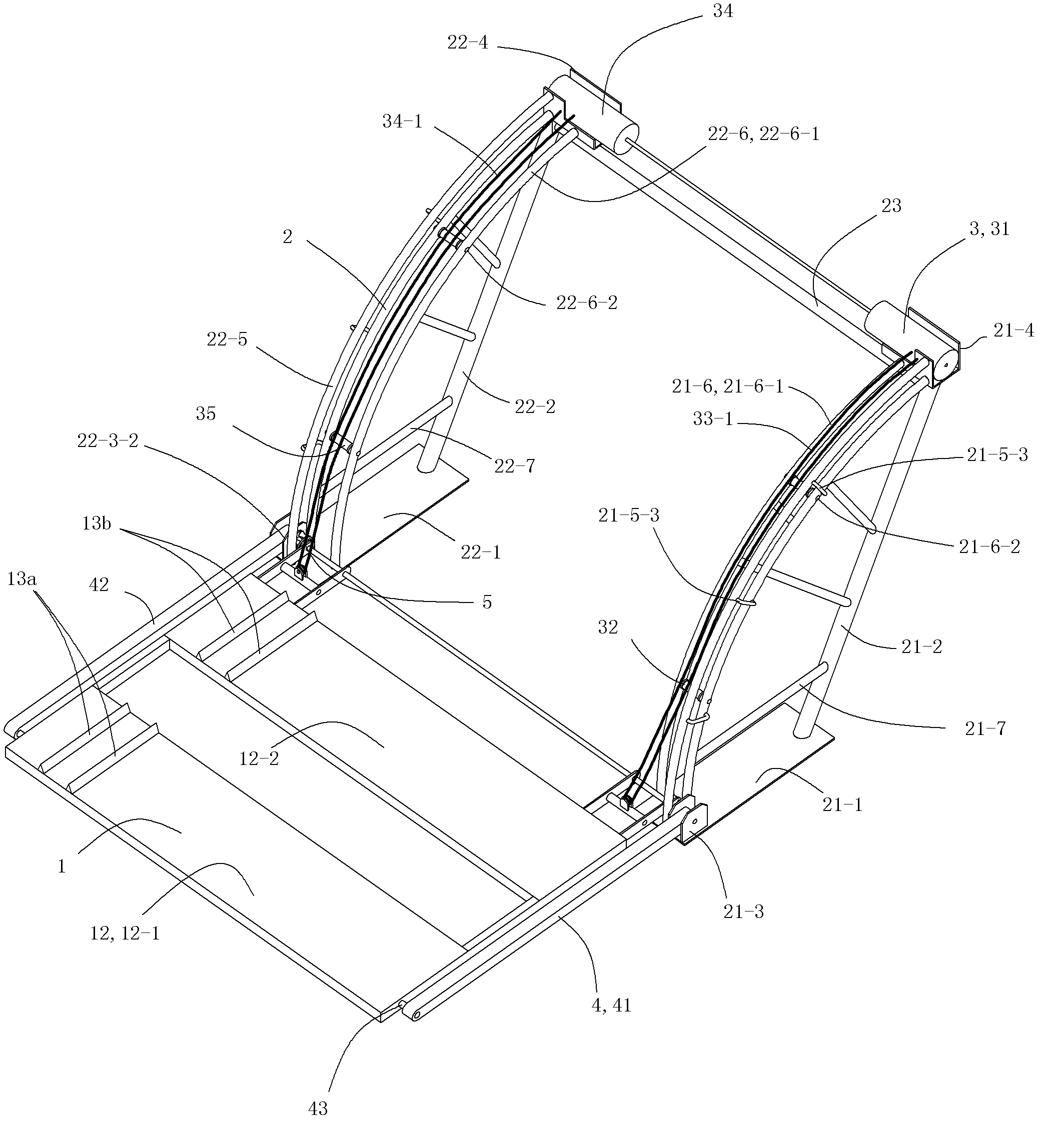
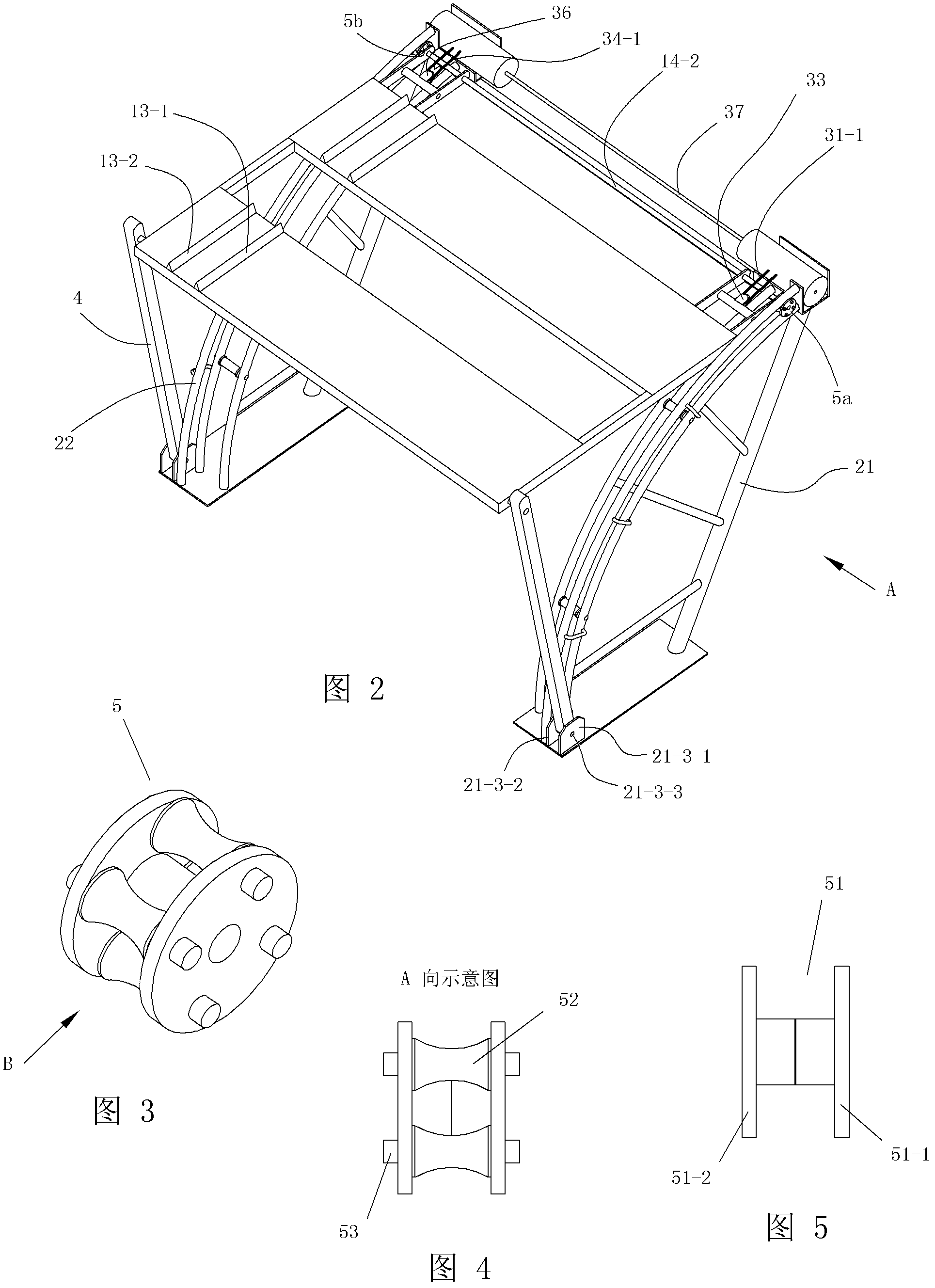
[0089] see figure 1 with figure 2 The parking device of this embodiment includes a parking platform 1, a main frame 2, a lifting device 3, a movable support column 4 and a roller assembly 5.

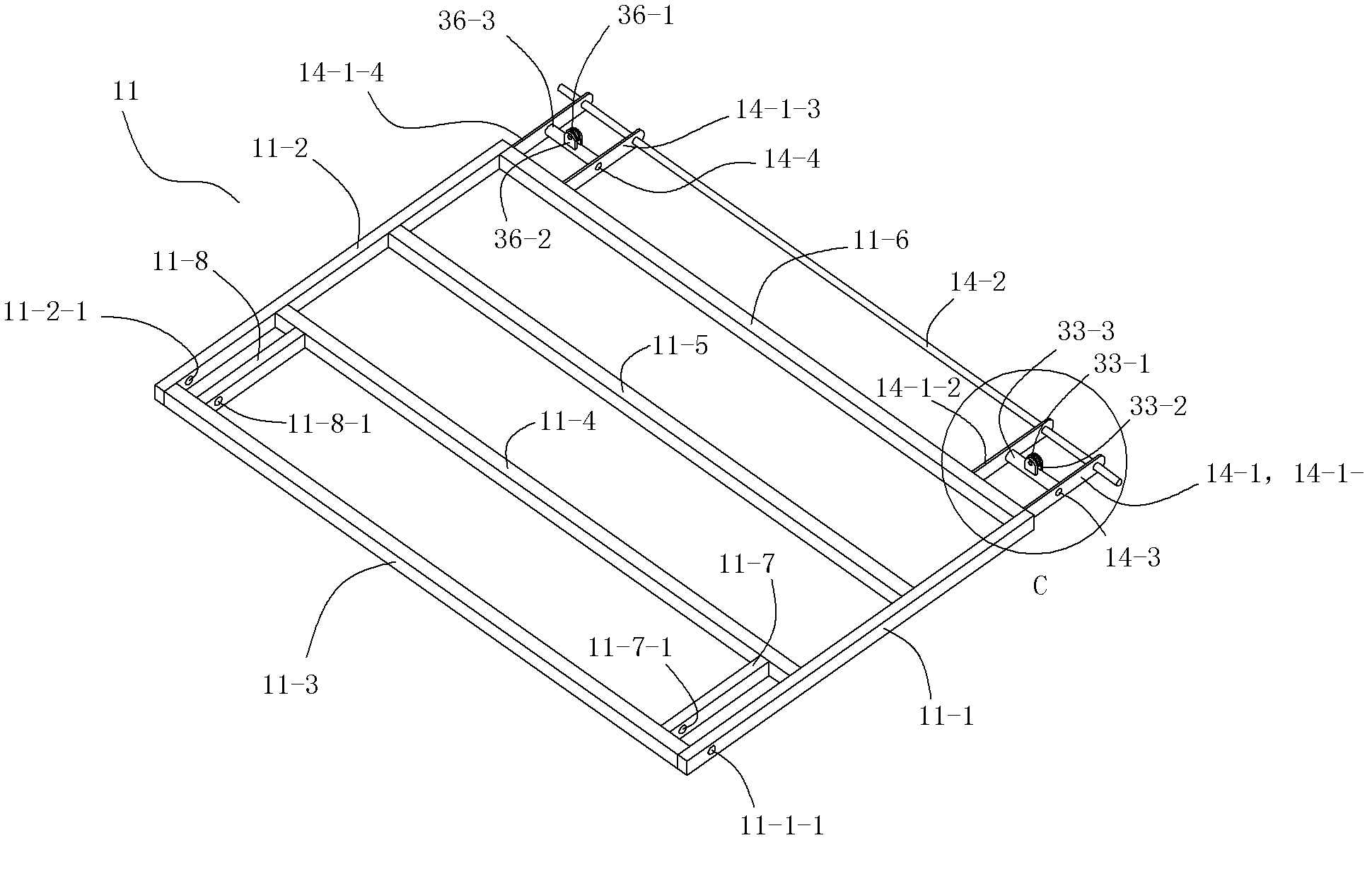
[0090] see figure 1 with Image 6 The parking platform 1 includes a frame 11, a load board 12, an anti-skid assembly 13 and a connecting frame 14.

[0091] The frame 11 is formed by welding a plurality of corresponding pipes in the same horizontal plane. The frame 11 includes a front cross beam 11-1, a rear cross beam 11-2, a first connecting beam 11-3, a second connecting beam 11-4, a third connecting beam 11-5, a fourth connecting beam 11-6, and a front pin shaft Beam 11-7 and rear pin shaft beam 11-8. The front cross beam 11-1, the front pin shaft beam 11-7, the rear pin shaft beam 11-8 and the rear cross beam 11-2 are all arranged in the left-right direction, and the front cross beam 11-1, the front pin shaft beam 11-7 and the rear pin The axle bea...

Embodiment 2

[0130] (Example 2, parking device)

[0131] The rest of this embodiment is the same as the first embodiment, and the difference is that the front and rear ends of the connecting beam 23 are detachably fixedly connected to the corresponding front side bracket 21 and the rear bracket 22.

[0132] see Picture 11 with Picture 12 The front side bracket 21 also includes a front connecting flange 21-8. The front connecting flange 21-8 is vertically arranged, and the front connecting flange 21-8 is welded and fixed to the upper part of the front main beam 21-2 of the front side bracket 21 by welding at the corresponding part of the front side. The rear bracket 22 also includes a rear connecting flange. The rear connecting flange is vertically arranged, and the rear connecting flange is welded and fixed to the upper part of the front side of the rear main beam 22-2 of the rear bracket 22 from the corresponding part of the rear side of the rear connecting flange. The front and rear ends ...


PUM


Abstract

The invention discloses a parking device, which comprises a parking platform and a lifting appliance. The parking device is characterized by further comprises a main rack, movable supporting columns and roller components. The main rack comprises a front-side support, a rear-side support and a connecting crossbeam. The front-side support and the rear-side support are arranged parallelly mutually from front to back, the connecting crossbeam is fixedly connected between the rear side of the upper portion of the front-side support and the front side of the upper portion of the rear-side support, and both the front-side support and the rear-side support are seated and fixedly connected onto a foundation during usage. Two ends of one side of the parking platform are respectively hinged on the corresponding movable supporting columns, and two ends of the other side of the parking platform are respectively arranged on the front-side support and the rear-side support correspondingly via the corresponding roller components. The parking platform is driven by a front-side winch and a rear-side winch of the lifting appliance to be capable of translating from a lower side position on the lower portion of the main rack to an upper side position on the upper portion of the main rack, or translating from the upper side position to the lower side position.

Description

Technical field [0001] The invention relates to a parking device. Background technique [0002] With the increasing number of family cars, the contradictions about car parking problems are also increasing. Difficulty in parking has become the primary problem for car owners. Usually the number of parking spaces in residential communities is limited, but the number of cars in the community is increasing. The parking spaces cannot meet the parking needs of all car owners. Some cars can only be forced to park on the greenery of the community or on the roads near the community. Destroy the greenery of the community and cause road congestion. [0003] Chinese Patent Document CN101457597A (Patent Application No. 200910028626.2) discloses "a parking device", which records: "The base 21 on which the parking device of the present invention is installed is set in the green belt 22 of a residential area, and the parking device is mainly composed of a parking platform 5 , Connecting rod 1, c...

Claims


Application Information

Patent Timeline
Patent Type & Authority Applications(China)
IPC IPC(8): E04H6/06
Inventor 陈跃平
Owner 陈跃平
Why Eureka
Try Eureka