Composite solid lubrication sprocket shaft group

A technology of solid lubrication and sprocket shaft, which is applied in the direction of engine lubrication, bearing components, shafts and bearings, etc. It can solve problems such as unreliable lubrication, damage to bearing retainers, and wear of bearing inner sleeves, so as to reduce wear, improve life, The effect of increasing the load capacity

Active Publication Date: 2016-12-14
鄂尔多斯市云新技术研究有限公司 +1
View PDF8 Cites 0 Cited by
  • Summary
  • Abstract
  • Description
  • Claims
  • Application Information

AI Technical Summary

Problems solved by technology

[0004] The purpose of the present invention is to provide a composite solid lubricated sprocket shaft group, which solves the problems of oil leakage, unreliable lubrication, excessive wear of the floating seal ring, abnormal wear of the inner sleeve of the bearing, damage of the bearing retainer, and wear of the spline in the sprocket shaft group. Excessive, gear coupling damage, etc.

Method used


Image

  • Composite solid lubrication sprocket shaft group
  • Composite solid lubrication sprocket shaft group
  • Composite solid lubrication sprocket shaft group

Examples


Embodiment 1

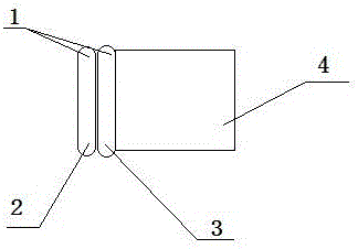
[0016] Such as figure 1 As shown, the core seal of the composite solid lubricated sprocket shaft assembly includes a floating sealing ring 1 and a sealing flange 4, and the floating sealing ring 1 is composed of two geometrically identical metal rings. One is the floating ring 3, which is fixed on the sealing flange 4; the other is the stationary ring 2, and the stationary ring 2 and the floating ring 3 are fitted together for relative movement to achieve a sealing effect.

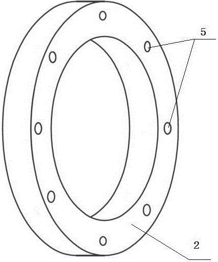
[0017] Such as figure 2 As shown, an annular latent pit 5 structure is adopted on the fitting surface of the stationary ring 2, the fitting surface of the floating ring 3 is smooth, the size of the latent pit 5 is Φ2.5mm*1mm, and the distance between adjacent latent pits 5 is 5mm. There is solid lubricant in latent pit 5.

[0018] When working, the stationary ring 2 and the floating ring 3 move relatively, and the ring-shaped latent pit 5 structure is used on the joint surface of the stationary ring 2 ...

Embodiment 2

[0020] The structure of this embodiment is basically the same as that of Embodiment 1, except that the bonding surface of the floating ring 3 adopts an annular latent pit 5 structure, and there is a solid lubricant in the latent pit 5, while the bonding surface of the stationary ring 2 is a smooth surface.

[0021] The joint surface of any one of the two metal rings of the floating sealing ring 1 adopts the annular latent pit 5 structure, which can achieve the expected effect in practical applications.

Embodiment 3

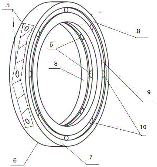
[0023] Such as image 3 As shown, the bearing 6 is a commonly used bearing, which is composed of an inner ring 7, an outer ring 8, a cage 9 and a rolling element 10, and a latent pit is used on the contact surface of the cage 9, the inner ring 7 and the outer ring 8 5 structure, there is solid lubricant in latent pit 5.

[0024] The size of the latent pits 5 is Φ2.5mm*1mm, and the distance between adjacent latent pits 5 is 5mm.

[0025] When working, the latent pit 5 structure is used on the cage 9 of the bearing 6 to ensure that the surface of the rolling element is fully compensated by the composite solid lubricant, so that the solid lubricant transferred on the motion track of the inner and outer rings of the bearing forms a firm and reliable composite lubricant. Solid lubricating film, which improves the load capacity of the sprocket shaft group bearings, reduces wear and improves the life of the bearings.


PUM


Abstract

The invention belongs to the field of operating machinery, and relates to a chain wheel shaft group, in particular to a composite solid lubricated chain wheel shaft group. It includes at least a floating sealing ring and a sealing flange. The floating sealing ring is two geometrically identical metal rings. The floating ring is fixedly connected to the sealing flange. The stationary ring fits the floating ring and the two move relative to each other. Its characteristics are: floating The bonding surface of the ring or the stationary ring is an annular latent pit structure, and there is a solid lubricant in the latent pit. It also includes a bearing, which is composed of an inner ring, an outer ring, a cage and a rolling element, and is characterized in that: the contact surface of the cage, the inner ring and the outer ring is a latent pit structure, and there is a solid lubricant in the latent pit. The design method of the composite solid lubricated sprocket shaft group solves the problems of oil leakage, unreliable lubrication, excessive wear of the floating seal ring, abnormal wear of the inner sleeve of the bearing, damage of the bearing retainer, excessive wear of the spline, and gear coupling in the sprocket shaft group. device damage, etc.

Description

technical field [0001] The invention belongs to the field of operating machinery, and relates to a chain wheel shaft group, in particular to a composite solid lubricated chain wheel shaft group. Background technique [0002] The sprocket shaft group of the bendable scraper conveyor and the scraper loader of the shearer is the key component of the fully mechanized mining equipment in the coal mine. The technical improvement related to it is directly related to the efficiency and benefit of the coal mine fully mechanized mining system. Since the first chain shearer was born in the UK in the 1940s, the oil leakage of the scraper sprocket shaft group has caused damage to this component, which has always been the crux of the technical progress of the coal shearer, especially with the With the rapid development of economy and society, the social production capacity of energy is constantly being promoted by demand, and the non-stop continuous operation of mechanical equipment that...

Claims


Application Information

Patent Timeline
Patent Type & Authority Patents(China)
IPC IPC(8): F16J15/34F16C33/38F16C33/46F16C33/66F16N1/00
Inventor 张军
Owner 鄂尔多斯市云新技术研究有限公司
Why Eureka
Try Eureka