Magnetic coupling resonance type wireless energy transmission device based on panel magnetic core

A technology of wireless energy transmission and flat magnetic core, applied in the direction of circuit devices, electromagnetic wave systems, electrical components, etc., to achieve the effect of improving transmission distance and efficiency, small size, and reducing operating frequency

Inactive Publication Date: 2012-07-25
HARBIN INST OF TECH
View PDF4 Cites 19 Cited by
  • Summary
  • Abstract
  • Description
  • Claims
  • Application Information

AI Technical Summary

Problems solved by technology

[0004] The present invention aims to solve the problem that the existing magnetic coupling resonant wireless energy transmission device can only transmit low-power energy, and provides a magnetic coupling resonant wireless energy transmission device based on a flat magnetic core

Method used


Image

  • Magnetic coupling resonance type wireless energy transmission device based on panel magnetic core
  • Magnetic coupling resonance type wireless energy transmission device based on panel magnetic core
  • Magnetic coupling resonance type wireless energy transmission device based on panel magnetic core

Examples


specific Embodiment approach 1

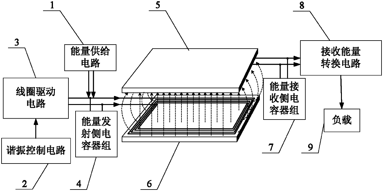
[0036] Specific implementation mode 1: the following combination figure 1 To explain this embodiment, the magnetic coupling resonance type wireless energy transmission device based on a flat magnetic core in this embodiment includes an energy supply circuit 1, and it also includes a resonance control circuit 2, a coil drive circuit 3, and an energy transmitting side capacitor bank 4 , Energy transmitting subsystem 5, energy receiving subsystem 6, energy receiving side capacitor bank 7, receiving energy conversion circuit 8,

[0037] The output DC voltage of the energy supply circuit 1 is used as the DC bus voltage V of the coil drive circuit 3 dc , The coil drive circuit 3 is under the control of the pulse drive signal generated by the resonance control circuit 2, the output frequency is f, and the amplitude is positive and negative V dc The AC square wave signal is applied to the resonance circuit composed of the energy transmitting side capacitor bank 4 and the transmitting coil...

specific Embodiment approach 2

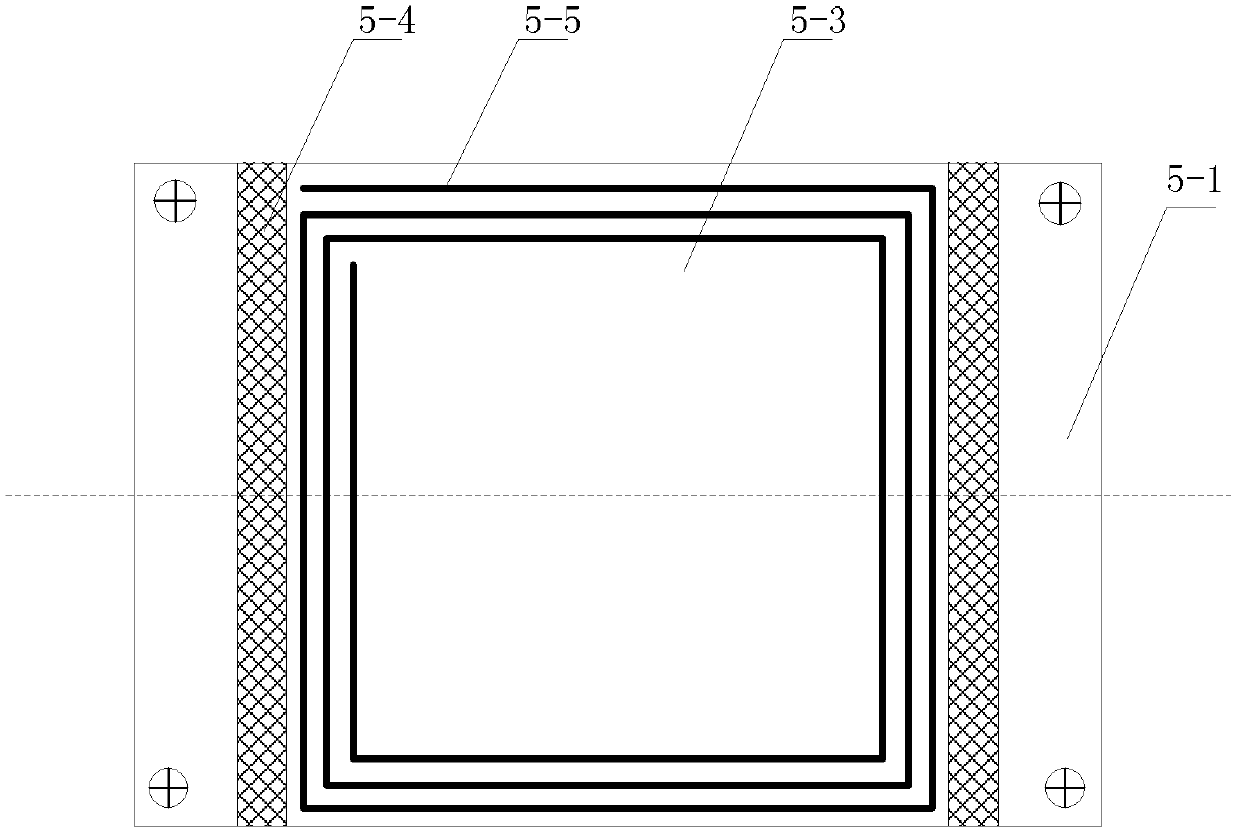
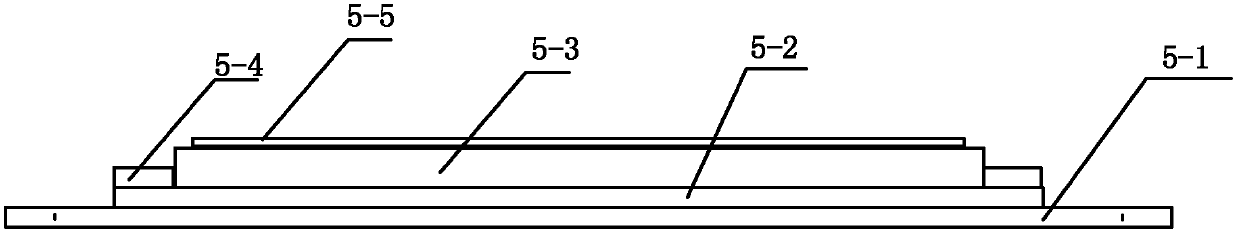
[0045] Specific implementation manner 2: the following combination Figure 2 to Figure 5 This embodiment is described. This embodiment is a further description of the first embodiment. The energy transmitting subsystem 5 and the energy receiving subsystem 6 have the same structure.

[0046] The energy transmitting subsystem 5 is composed of a shielded aluminum plate 5-1, an insulating plate 5-2, a flat magnetic core 5-3, two card plates 5-4 and a transmission coil 5-5.

[0047] An insulating plate 5-2 is set in the center on the shielding aluminum plate 5-1, and a flat magnetic core 5-3 is set in the center on the insulating plate 5-2. Both ends of the flat magnetic core 5-3 are respectively fixed to the insulating plate through a clamping plate 5-4. On 5-2, the transmission coil 5-5 is fixed on the flat magnetic core 5-3;

[0048] The energy transmitting subsystem 5 and the energy receiving subsystem 6 are arranged oppositely, and a uniform air gap is left between the energy transmi...

specific Embodiment approach 3

[0051] Specific implementation manner three: the following combination Figure 2 to Figure 5 To illustrate this embodiment, this embodiment is a further description of the second embodiment. The transmission coil 5-5 is fixed on the air gap side surface of the flat magnetic core 5-3, and the transmission coil 5-5 is spirally wound A plate-shaped coil, and the shape of the plate-shaped coil is the same as that of the plate core 5-3; or the transmission coil 5-5 is spirally wound on the plate core 5-3; the energy transmitting subsystem 5 The air gap side surfaces of the flat magnetic core 5-3 of the energy receiving subsystem 6 and the energy receiving subsystem 6 are respectively regular polygons, circles or ellipses.

[0052] The transmission coil 5-5 on the flat magnetic core 5-3 can be divided into two modes: plane spiral and winding spiral.

[0053] The plate core 5-3 can be selected to have a symmetrical shape.


PUM


Abstract

A magnetic coupling resonance type wireless energy transmission device based on a panel magnetic core belongs to the technical field of magnetic coupling resonance type wireless energy transmission and solves the problem that existing magnetic coupling resonance type wireless energy transmission devices can be only used for low-power energy transmission. The output direct voltage of an energy supply circuit of the device is used as the direct-current busbar voltage Vdc for a coil drive circuit, the coil drive circuit outputs alternating-current square signals and applying the same to a resonance circuit to enable a transmitting coil to generate magnetic field energy, and the resonance circuit consists of an energy transmitting side capacitor bank and the transmitting coil of an energy transmitting subsystem. A magnetic field of the energy transmitting subsystem and a resonance circuit consisting of an energy receiving side capacitor bank and a receiving coil of an energy receiving subsystem are used for magnetic coupling resonance to generate electric energy on the receiving coil of the energy receiving subsystem, and the electric energy is transmitted to an energy conversion circuit which converts input signals of the electric energy into direct-current power voltage signals required by a load. The magnetic coupling resonance type wireless energy transmission device is used for wireless energy transmission.

Description

Technical field [0001] The invention relates to a magnetic coupling resonance type wireless energy transmission device based on a flat magnetic core, belonging to the technical field of magnetic coupling resonance type wireless energy transmission. Background technique [0002] Wireless energy transmission technology has attracted much attention due to its safety, convenience and broad application prospects, and has gradually begun to replace traditional wire energy transmission methods. [0003] Wireless energy transmission using electromagnetic fields can be mainly divided into electromagnetic induction and magnetic coupling resonance. Electromagnetic induction wireless energy transmission generally uses traditional E-type or can-type magnetic cores, which are often relatively large in size and weight, and the transmission distance is relatively short, which greatly limits its application. The magnetic coupling resonant wireless energy transmission device without a magnetic core...

Claims


Application Information

Patent Timeline
Patent Type & Authority Applications(China)
IPC IPC(8): H02J17/00H02J50/12
Inventor 朱春波逯仁贵苏琮皓毛世通程志远张剑韬李坤
Owner HARBIN INST OF TECH
Why Eureka
Try Eureka