Lead core laminated rubber support seat capable of bearing tensile force

A technology of laminated rubber bearings and lead cores, which is applied to building components, earthquake resistance, construction, etc., can solve problems such as damage, poor tensile bearing capacity, and damage to seismic isolation layers, so as to ensure safety, facilitate construction, and protect structures safe effect

Inactive Publication Date: 2012-08-01
吕西林 +1
View PDF9 Cites 11 Cited by
  • Summary
  • Abstract
  • Description
  • Claims
  • Application Information

AI Technical Summary

Problems solved by technology

However, when the height-width ratio of the structure is large, the vertical seismic action is large, or the horizontal shear deformation of the laminated rubber bearing is large, tensile stress will be generated in the whole or part of the bearing section, while the ordinary rubber isolation bearing The tensile bearing capacity is very poor, and damage may occur under a small tensile stress, which may lead to the destruction of the entire isolation layer

Method used


Image

  • Lead core laminated rubber support seat capable of bearing tensile force
  • Lead core laminated rubber support seat capable of bearing tensile force
  • Lead core laminated rubber support seat capable of bearing tensile force

Examples


Embodiment 1

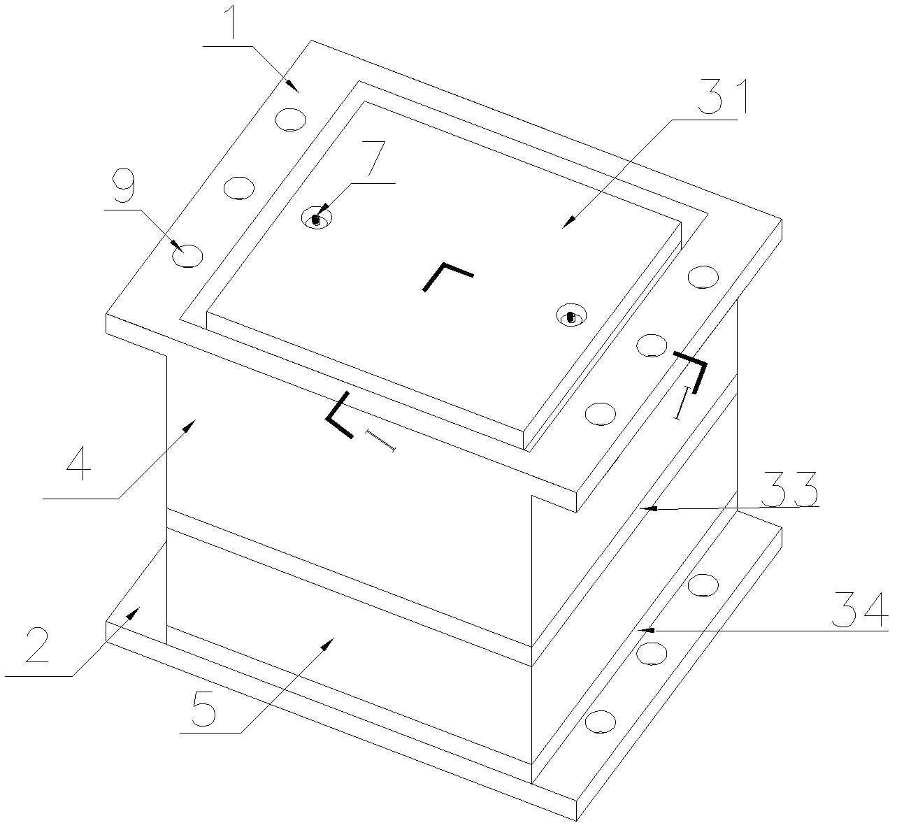
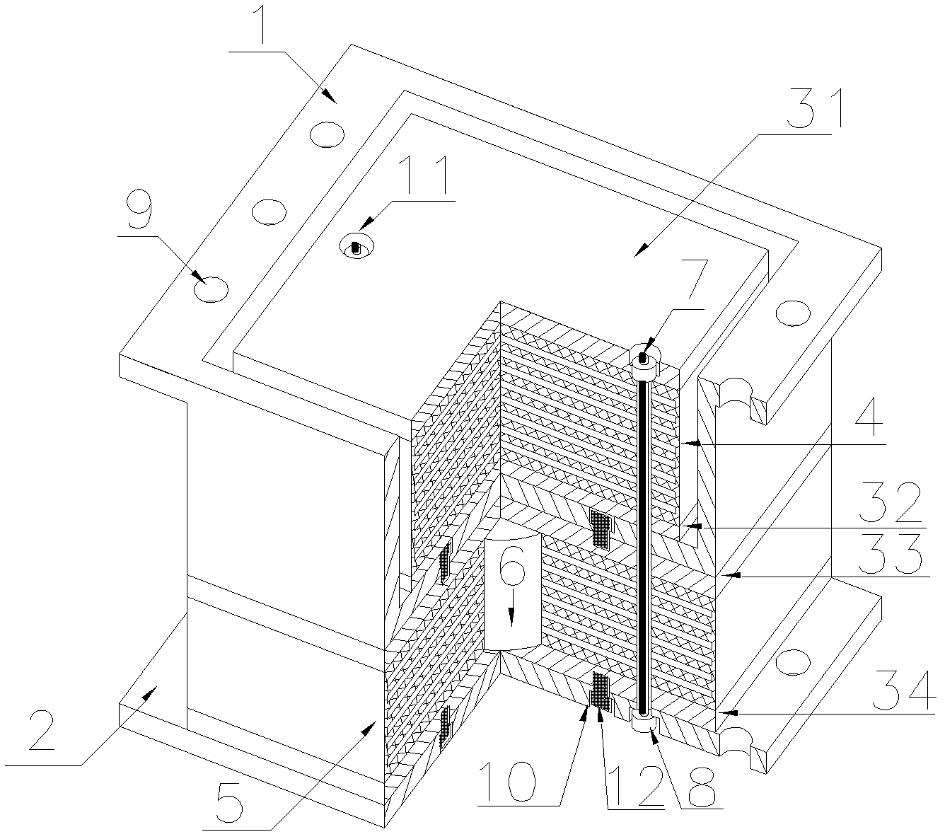
[0034] Such as figure 1 with 2 Shown are the structural diagram and cross-sectional view of Embodiment 1 of the present invention, respectively.

[0035] The laminated rubber bearing is a square bearing. A laminated rubber bearing, comprising an upper connecting piece 1 and a lower connecting plate 2, the upper connecting piece 1 is located above the lower connecting plate 2, the upper connecting piece 1 is provided with a pressure rubber pad 4, the upper connecting piece 1 and the lower connecting plate 2 A shearing rubber cushion 5 is arranged between the lower connecting plates 2 , and the compressed rubber cushion 4 and the shearing rubber cushion 5 are integrally fixed by steel strands 7 .

[0036] The pressure rubber cushion layer 4 is a standard laminated rubber layer.

[0037] An upper sealing plate 31 and a lower sealing plate 32 are respectively bonded to the upper and lower surfaces of the pressure rubber cushion 4 , wherein the lower sealing plate 32 is located ...

Embodiment 2

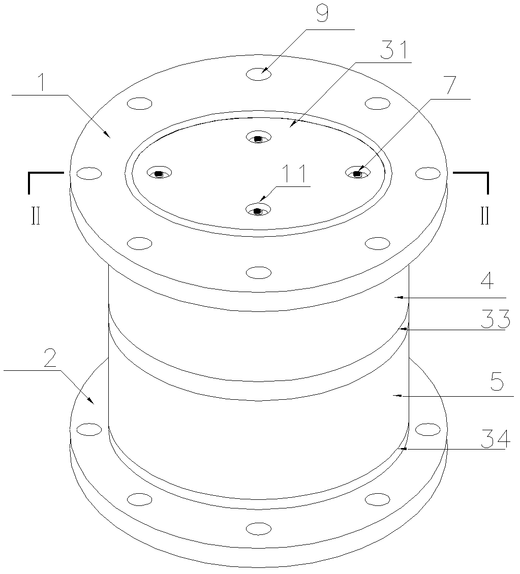
[0047] image 3 with Figure 4 It is the embodiment of the round support in Embodiment 2 of the present invention, and its implementation method is the same as that of the square support in Embodiment 1 above.

[0048] A laminated rubber bearing, comprising an upper connecting piece 1 and a lower connecting plate 2, the upper connecting piece 1 is located above the lower connecting plate 2, the upper connecting piece 1 is provided with a pressure rubber pad 4, the upper connecting piece 1 and the lower connecting plate 2 A shearing rubber cushion 5 is arranged between the lower connecting plates 2 , and the compressed rubber cushion 4 and the shearing rubber cushion 5 are integrally fixed by steel strands 7 .

[0049] The pressure rubber cushion layer 4 is a standard laminated rubber layer.

[0050] An upper sealing plate 31 and a lower sealing plate 32 are respectively bonded to the upper and lower surfaces of the pressure rubber cushion 4 , wherein the lower sealing plate ...


PUM


Abstract

The invention belongs to the field of buildings and relates to a laminated rubber support seat. The laminated rubber support seat comprises an upper connecting member (1) and a lower connecting plate (2), wherein the upper connecting member (1) is positioned above the lower connecting plate (2); a stressed rubber gasket layer (4) is arranged in the upper connecting member (1); a shear press rubber gasket layer (5) is arranged between the upper connecting member (1) and the lower connecting plate (2); and the stressed rubber gasket layer (4) is fixedly connected with the shear press rubber gasket layer (5) through pulling and tying a steel stranded wire (7). When earthquake occurs, the shear press rubber gasket layer can generate vertical and horizontal deformation to bear an upper structure load and a vertical earthquake pressure; and the stressed rubber gasket layer bears the vertical earthquake tensile force generated at the support seat, so that the seismic isolation effect of a seismic isolation support seat can be achieved and the rubber support seat is prevented from being damaged when the support seat generates the tensile force.

Description

technical field [0001] The invention belongs to the technical field of vibration isolation and shock absorption of building structures, and relates to a laminated rubber bearing. technical background [0002] The so-called base isolation structure is to install a seismic isolation device between the structure and the foundation to prolong the natural vibration period of the structure, increase the structural damping, and prevent the transmission of seismic energy to the upper structure in order to reduce the seismic impact of the structure. resulting in a structural system. The lead core laminated rubber bearing is a widely used seismic isolation device. It is installed between the structure and the foundation during use, so that it can not only bear the vertical load of the upper structure, but also block the upward vibration of seismic energy due to its lateral flexibility. Transmission, but also can consume and absorb seismic energy to protect the safety of the superstru...

Claims


Application Information

Patent Timeline
IPC IPC(8): E04B1/36E04B1/98
Inventor 吕西林王栋
Owner 吕西林
Why Eureka
Try Eureka