Construction method of large-height small-sized cast-in-place concrete beam slab

A construction method and concrete technology, which are applied in the fields of formwork/formwork/work frame, on-site preparation of building components, and processing of building materials, etc., can solve the problems of uneconomical, long and slender support frame, and many unsafe factors.

Inactive Publication Date: 2012-08-01
河北省第二建筑工程有限公司
View PDF3 Cites 5 Cited by
  • Summary
  • Abstract
  • Description
  • Claims
  • Application Information

AI Technical Summary

Problems solved by technology

If you use the conventional floor-standing full-house scaffolding, that is, use the scaffolding from the ground to the fourth floor to support the pouring formwork, you will use a large number of scaffolding pipes and scaffolding boards, which will cost a lot of labor and material costs, resulting in costly measures. Far greater than the cost of the concrete beam-slab structure itself, it is very uneconomical and greatly increases construction costs
Moreover, the slenderness of the supporting frame of the pouring formwork is relatively large, the stability of the frame body is poor, and there are many unsafe factors.

Method used


Image

  • Construction method of large-height small-sized cast-in-place concrete beam slab
  • Construction method of large-height small-sized cast-in-place concrete beam slab
  • Construction method of large-height small-sized cast-in-place concrete beam slab

Examples


Embodiment Construction

[0023] Below in conjunction with accompanying drawing, the present invention is described in further detail:

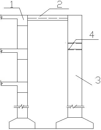
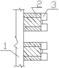
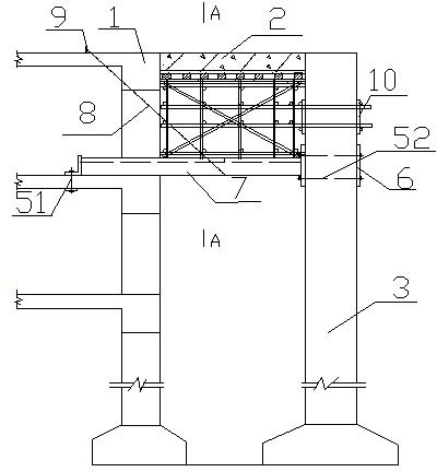
[0024] The construction method of small cast-in-place concrete beams and slabs with large height, such as image 3 , Figure 4 As shown, it includes a floor foundation constructed of multi-layer slabs, and poured concrete frame columns are set on one side of the floor. According to construction requirements, such as figure 1 , figure 2 As shown, the cast-in-place concrete beam slab 2 must be poured between the floor slab 1 of a certain floor and the concrete frame column 3 of the corresponding floor. Described construction method comprises the steps:

[0025] a. Bolt holes are reserved on the concrete frame column, and the position of the bolt hole is opposite to the lower floor of the floor where the concrete beam slab needs to be poured; that is, if the concrete beam slab is to be poured at the seventh floor, the bolt Holes are reserved on the concrete frame c...


PUM

PropertyMeasurementUnit
Lengthaaaaaaaaaa

Abstract

The invention discloses a construction method of a large-height small-sized cast-in-place concrete beam slab. The large-height small-sized cast-in-place concrete beam slab comprises a floor foundation built by using multiple layers of floor slabs and a concrete framework column. The method comprises the following steps of: preserving a bolt hole on a concrete framework column which is opposite to a lower layer slab of the floor on which a concrete beam slab is required to be poured; arranging a channel steel support beam between the lower layer slab of the floor on which the concrete beam slab is required to be poured and the preserved bolt hole, and connecting and fixing the two ends of the support beam by using bolts; arranging a steel wire rope on the middle part of the support beam, and fixing the other end of the steel wire rope on a hoisting ring embedded into the floor on which the concrete beam slab is required to be poured; building a template support beam on the support beam; fixedly arranging a template on the template support frame; building a protective net; and pouring. Due to the adoption of the construction method, the building height of a scaffold is reduced greatly, a large quantity of frame pipes and fasteners are saved, and material cost, manual installation cost and detaching cost are reduced.

Description

technical field [0001] The invention relates to a construction method of a cast-in-place reinforced concrete frame beam-slab structure during building construction, in particular to a construction method of a large-height and small-scale cast-in-place concrete beam-slab structure. Background technique [0002] The main body of the building is usually poured after the first floor is poured, and the upper floor is poured, and the floor slab and concrete frame columns are raised at the same time. But some places of the building directly lead to a very high place from underground, as there is no pouring concrete beam slab in the very long distance between the first floor and the third floor, only a concrete beam slab needs to be poured on the fourth floor. This is a pouring structure that often encounters large-height and small-scale cast-in-place concrete beams and slabs in construction projects. This kind of concrete beams and slabs has a large space height, a small span, and ...

Claims


Application Information

Patent Timeline
IPC IPC(8): E04G21/00E04G11/48
Inventor 赵玉淼侯永忠张哲峰赵刚
Owner 河北省第二建筑工程有限公司
Why Eureka
Try Eureka