
Swing-mechanical wave power generation device

A wave power generation and mechanical technology, applied in mechanical equipment, hydropower generation, ocean power generation, etc., can solve problems such as installation difficulties, increase the length of the transmission chain, and low wave utilization rate, so as to improve stability and efficiency and simplify machinery Transmission chain, effect of reduction in manufacturing cost

Inactive Publication Date: 2012-08-01
HARBIN ENG UNIV
View PDF4 Cites 25 Cited by
  • Summary
  • Abstract
  • Description
  • Claims
  • Application Information

AI Technical Summary

Problems solved by technology

This invention has two deficiencies: 1. The fluctuation frequency of waves is low, so the rotational speed on the power output shaft is not high. If no speed increase or other means are used, the power generation efficiency is quite low and the practicability is poor; 2. .Due to the long fluctuation period and low frequency of waves, the rotation of the power output shaft must be intermittent. If no mechanical energy storage device is added, its efficiency is extremely low
This invention has two deficiencies: 1. The wave power plate only absorbs the driving force of the wave, and does not make good use of the buoyancy of the wave, so the wave utilization rate is low; 2. The device adopts a speed-up mechanism, which is difficult to install and difficult to maintain Large, the length of the transmission chain is increased, the efficiency of the whole device is greatly reduced, and the starting torque at the input end is greatly increased

Method used


Image

  • Swing-mechanical wave power generation device
  • Swing-mechanical wave power generation device
  • Swing-mechanical wave power generation device

Examples


Embodiment Construction

[0020] The present invention is described in more detail below in conjunction with accompanying drawing example:

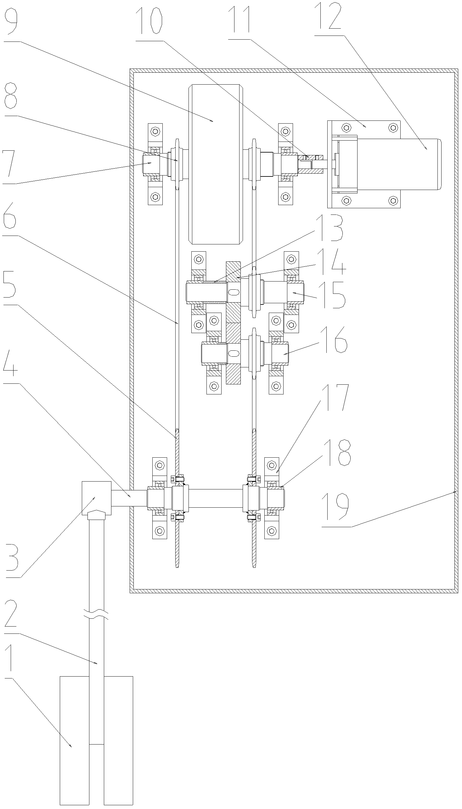
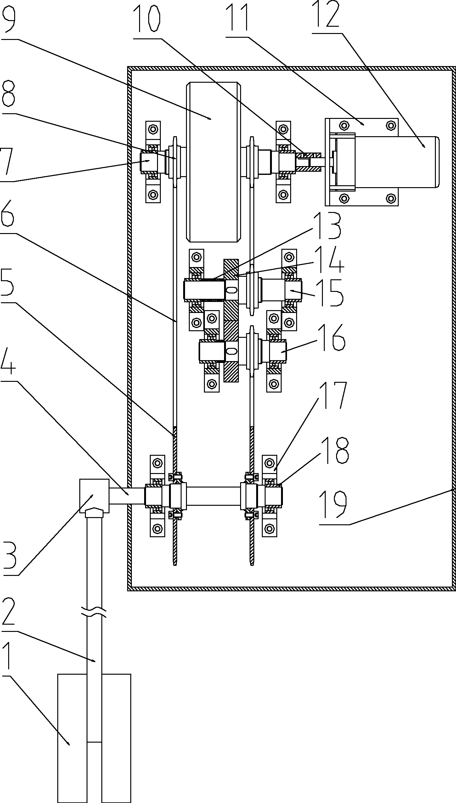
[0021] combine Figure 1~2 , a swinging mechanical wave power generation device, the device converts the up and down movement of waves into one-way rotation on the 12 shafts of a low-speed generator to drive the low-speed generator to generate electric energy. Its main structure includes a box body 19, a "duck belly" wave collecting buoy 1, a one-way motion conversion mechanism, an energy storage flywheel 9 and a low-speed generator 12. "Duck belly type" wave collection float 1 uses a connecting rod 2 to be connected to the input shaft 4 side of the one-way motion conversion mechanism, the low-speed generator 12 is connected to the output shaft 7 side of the one-way motion conversion mechanism, and the energy storage flywheel 9 is installed on The output shaft 7 , the one-way motion conversion mechanism and the low-speed generator 12 are installed on the casing 1...


PUM


Abstract

The invention provides a swing-mechanical wave power generation device, which comprises a case, a generator, an energy-storage flywheel, a one-way movement transfer mechanism, a floater and a connecting rod. The generator, the energy-storage flywheel and the one-way movement transfer mechanism are arranged in the case, the energy-storage flywheel is arranged on an output shaft of the one-way movement transfer mechanism, the generator is connected with the output shaft of the one-way movement transfer mechanism, and the floater is connected with an input shaft of the one-way movement transfer mechanism through the connecting rod. The wave collecting floater is in the shape of a duck belly, so that heaving and rolling movements of waves can be effectively captured. The one-way movement transfer mechanism is adopted to transfer the swing of the duck-belly type wave collecting floater into one-way movement on the output shaft, so that the use efficiency of the wave energy can be greatly increased. The energy-storage flywheel is arranged on the output shaft, so that the output on the output shaft can be more stable, and the stability and efficiency of the system is improved.

Description

technical field [0001] The invention relates to a clean energy generating device. Background technique [0002] The use of ocean energy is the direction of energy research in the world today. Especially in the situation where energy is related to national security, energy is gradually depleted and environmental conditions are deteriorating, how to effectively utilize resource-rich and renewable marine resources is very important. At present, the existing mechanical wave power generation device mainly uses the movement of waves to push the active parts of the device - rafts, floats, etc., to compress (drive) intermediate media such as oil, water, air, etc., and push the conversion power generation device to generate electricity through the intermediate medium. . [0003] Chinese patent application number 200710191545.5 discloses a wave power generation device, which is provided with a buoyant device on the transmission shaft, and the gear and sprocket on the transmission sh...

Claims


Application Information

Patent Timeline
IPC IPC(8): F03B13/16F03B17/06
CPCY02E10/38Y02E10/28Y02E10/30
Inventor 张立勋尉越啸梁迎彬刘小红裴新平
Owner HARBIN ENG UNIV
Learn More