Cooling device for condenser of central air conditioning system

A central air-conditioning system and cooling device technology, applied in the direction of air-conditioning systems, ventilation systems, heat recovery systems, etc., can solve the problems of lower COP value, high operating cost, and small cooling capacity of refrigeration units, so as to reduce operating costs and equipment cost, the effect of reducing the condensation temperature

Inactive Publication Date: 2012-08-01
CHONGQING UNIV
View PDF5 Cites 7 Cited by
  • Summary
  • Abstract
  • Description
  • Claims
  • Application Information

AI Technical Summary

Problems solved by technology

However, since the cooling water mainly absorbs the heat of the refrigerant in the form of sensible heat of water, the cooling capacity of the cooling water is limited by the outdoor ambient temperature and its own characteristics, and its cooling capacity is small. In order to ensure a reliable cooling effect, You can only increase the flow and velocity of the cooling water, which not only requires a cooling water pump with a relatively large power and a water pipe with a larger diameter, but also the power of the cooling fan in the cooling tower will also increase accordingly. Because the inlet temperature of the cooling water is relatively high, the condensation temperature of the refrigeration unit in the air conditioning system is also relatively high, the COP value of the refrigeration unit decreases, and the operating energy consumption of the air conditioning system increases
That is to say, the cooling device of the condenser in the existing central air-conditioning system not only has the disadvantages of large energy consumption and high operating cost, but also has poor cooling effect, which makes the COP value of the refrigeration unit smaller and increases the air-conditioning capacity. Operating energy consumption of the system

Method used


Image

  • Cooling device for condenser of central air conditioning system
  • Cooling device for condenser of central air conditioning system
  • Cooling device for condenser of central air conditioning system

Examples


Embodiment Construction

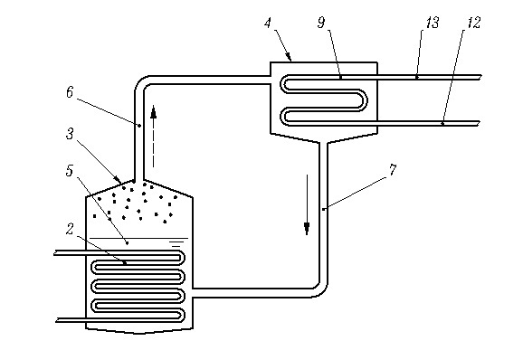
[0012] A cooling device for a condenser in a central air-conditioning system (refer to figure 1 ), the device includes a phase change generator 3, a gas pipe 6 connected to the top of the phase change generator 3 at one end, a heat recovery device 4 connected to the other end of the gas pipe 6, one end connected to the bottom of the heat recovery device 4 and the other One end is connected to the liquid pipe 7 at the bottom of the phase change generator 3; wherein, the end of the gas pipe 6 connected to the heat recovery device 4 is connected to the upper part of the heat recovery device 4, and a heat exchange coil is installed in the heat recovery device 4 9. One end of the heat exchange coil 9 is connected to the cold water inlet pipe 12, and the other end is connected to the hot water outlet pipe 13; the condenser 2 in the central air-conditioning system is installed in the lower part of the phase change generator 3. There is a gas-liquid phase-change material 5 submerged i...


PUM


Abstract

A cooling device for a condenser of a central air conditioning system comprise a phase change generator, an air pipe, a thermal recoverer and a liquid pipe, wherein one end of the air pipe is connected at the top of the phase change generator, the other end of the air pipe is connected with the thermal recoverer, one end of the liquid pipe is connected at the bottom of the thermal recoverer, the other end of the liquid pipe is connected with the lower portion of the phase change generator, one end of the air pipe connected with the thermal recoverer is connected at the upper portion of the thermal recoverer, a heat exchange coil is positioned in the thermal recoverer, one end of the heat exchange coil is connected with a cold water inlet pipeline, the other end of the heat exchange coil is connected with a hot water outlet pipe, the condenser is positioned at the lower portion in the phase change generator, air-liquid phase change materials are filled in the phase change generator and submerges the condenser in liquid state, and phase change temperature of the air-gas phase change materials is 25 DEG C to 35 DEG C in standard atmospheric pressure. The cooling device for the condenser of the central air conditioning system is low in energy consumption and good in cooling effect.

Description

technical field [0001] The invention relates to a central air-conditioning system, in particular to a device for cooling a condenser in the central air-conditioning system. Background technique [0002] The refrigeration unit in the air conditioning system includes an evaporator, a compressor, a condenser, and a throttling device, in which there is a refrigerant that circulates "carrying heat" driven by the compressor. Among them, the condenser is a heat exchange device used to cool the refrigerant (in a state of high temperature and high pressure when entering the condenser)—specifically, the condenser is cooled with a cooling medium to exchange heat between the refrigerant and the cooling medium, and finally play a role The role of cooling refrigerant. For the central air-conditioning system used in large buildings, the cooling medium used to cool the condenser is water, so it is commonly called "water cooling". The water-cooled system includes a cooling water pump that ...

Claims


Application Information

Patent Timeline
Patent Type & Authority Applications(China)
IPC IPC(8): F24F13/30F28D15/02F24F12/00
CPCY02B30/563Y02B30/56
Inventor 串禾蒲清平周杰刘正清黄育华王小艳詹武刚郑洁
Owner CHONGQING UNIV
Why Eureka
Try Eureka