
Frequency measuring method and frequency measuring system

A frequency measurement and clock frequency technology, applied in the field of electronics, can solve the problems of poor measurement accuracy and poor accuracy, and achieve the effect of improving measurement accuracy

Active Publication Date: 2012-08-01
ZHEJIANG SUPCON TECH
View PDF6 Cites 15 Cited by
  • Summary
  • Abstract
  • Description
  • Claims
  • Application Information

AI Technical Summary

Problems solved by technology

That is to say, for the measurement frequency method, there is a counting error of ±1 input signal within the unit timing time, so the relative error generated by it is about ±1 / N, where N is the measured input signal within the unit timing time It can be seen that the measurement accuracy of this method is poor at low frequencies; for the measurement cycle method, correspondingly, within the cycle time of the input signal, there is a counting error of ±1 reference pulse used, so the relative The error is about ±1 / M, where M is the number of reference pulses measured within the period of the input signal. It can be seen that this method has poor measurement accuracy at high frequencies
[0004] To sum up, both methods have the problem of poor accuracy in some cases, so it is necessary to provide a frequency measurement method with high measurement accuracy regardless of high frequency or low frequency

Method used


Image

  • Frequency measuring method and frequency measuring system
  • Frequency measuring method and frequency measuring system
  • Frequency measuring method and frequency measuring system

Examples


Embodiment Construction

[0055] In order to make the purpose, technical solutions and advantages of the embodiments of the present invention clearer, the technical solutions in the embodiments of the present invention will be clearly and completely described below in conjunction with the drawings in the embodiments of the present invention. Obviously, the described embodiments It is a part of embodiments of the present invention, but not all embodiments. Based on the embodiments of the present invention, all other embodiments obtained by persons of ordinary skill in the art without making creative efforts belong to the protection scope of the present invention.

[0056] An embodiment of the present invention provides a frequency measurement method to improve measurement accuracy in high frequency or low frequency measurement.

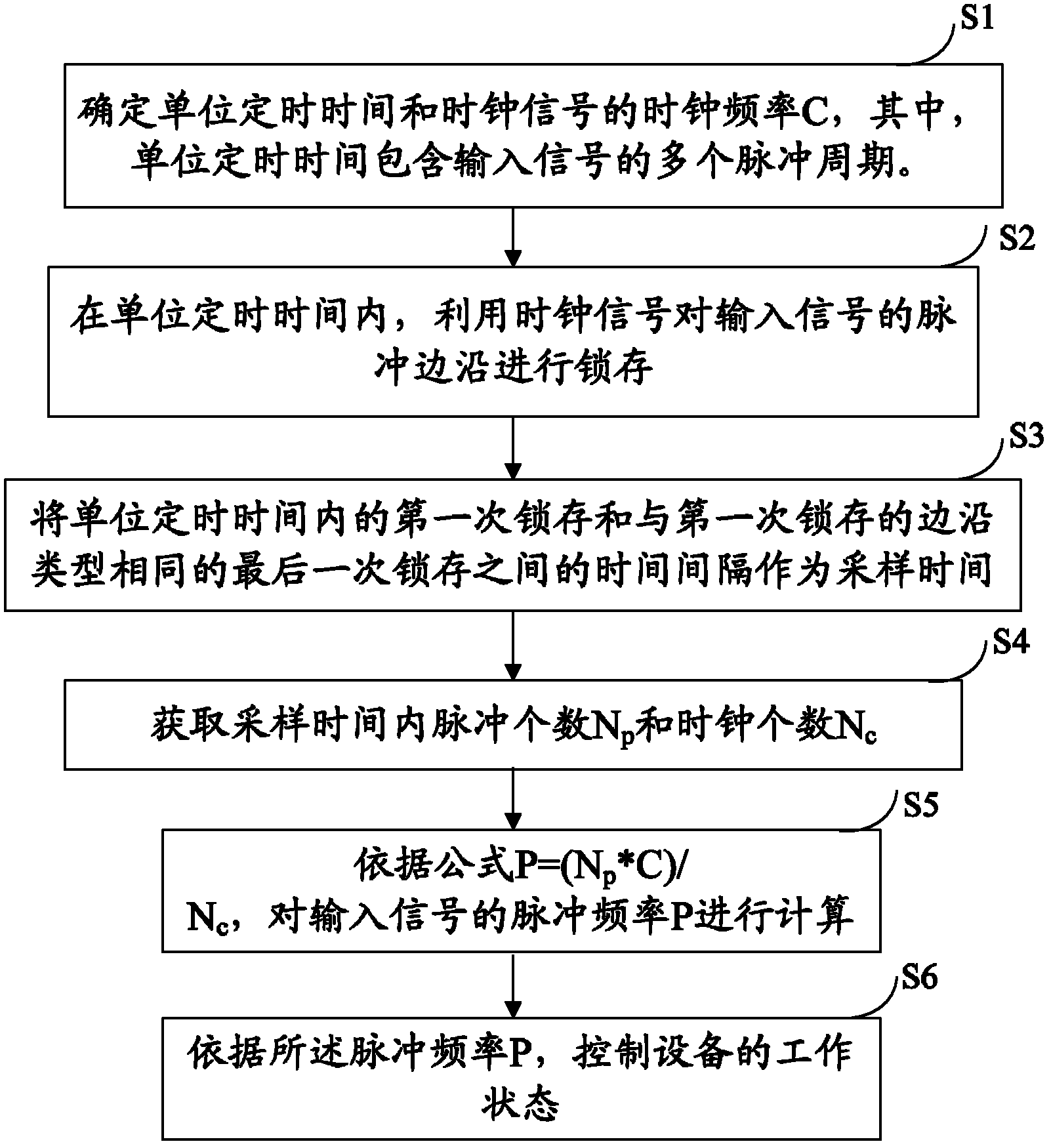
[0057] See figure 1 , which shows a flowchart of the above-mentioned frequency measurement method, at least including the following steps:

[0058] S1. Determine the unit tim...


PUM


Abstract

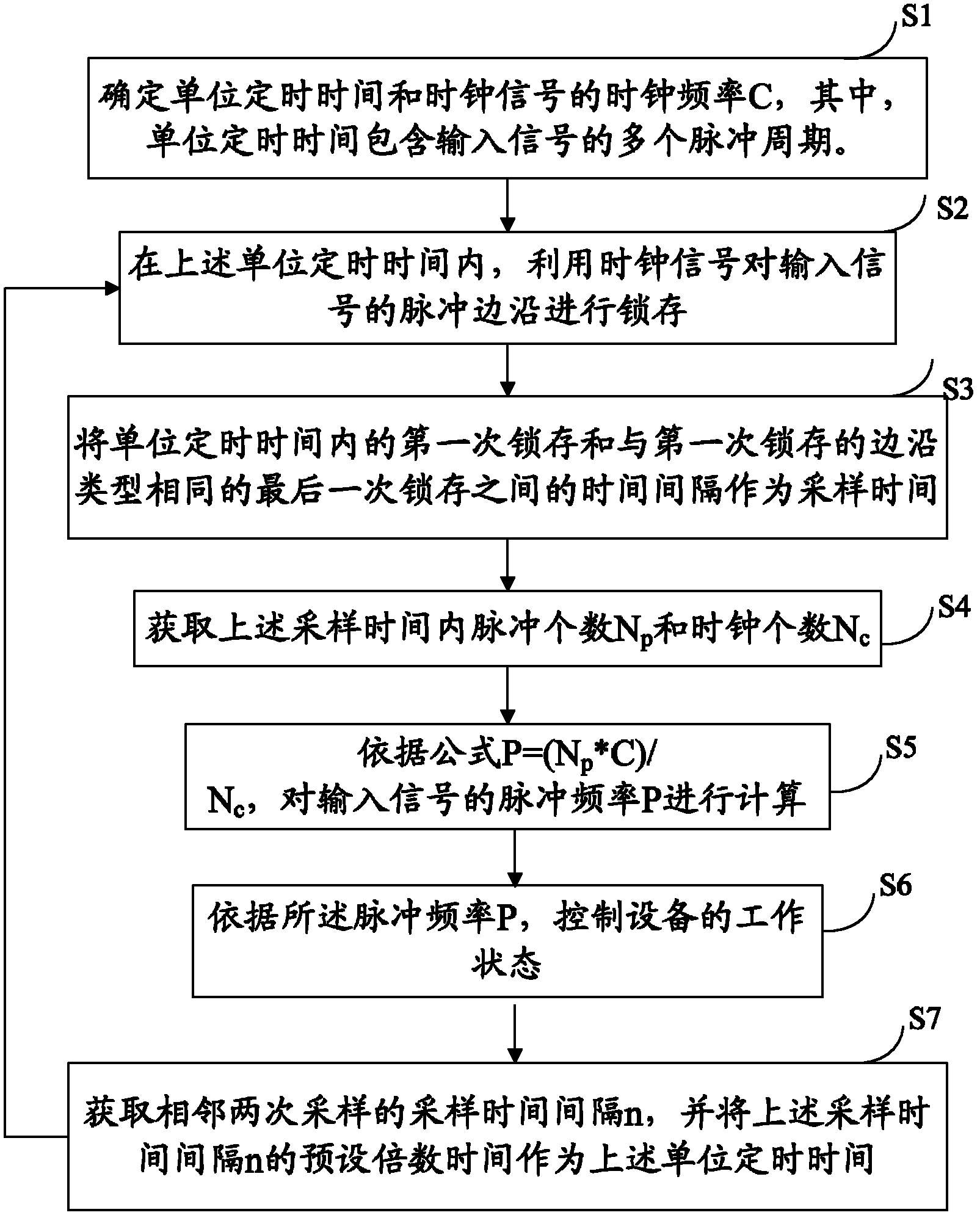
The invention discloses a frequency measuring method and a frequency measuring system. The frequency measuring method includes: latching pulse edges of input signals by means of clock signals to acquire pulse number Np and clock number Nc in sampling time, and computing pulse frequency P according to P=(NpxC) / Nc, wherein relative error by the frequency measuring method is + / -1 / Nc. When in low frequency, the relative error + / -1 / Np corresponding to + / - pulse signals in existing frequency measuring method is converted into + / -1 / Nc equivalently, while the clock number Nc is much higher than the pulse number Np, namely + / -1 / Nc is much smaller than + / -1 / Np, and accordingly, accuracy is improved. When in high frequency, by setting reasonable unit timing time and being compared with existing period measuring method, the Nc is increased along with prolonging of periods of input signals in the unit timing time, while + / - / Nc is reduced, and accuracy is improved as well. Therefore, when in high frequency and low frequency, the frequency measuring method is higher in measuring accuracy as compared with the existing measuring method.

Description

technical field [0001] The invention belongs to the field of electronic technology, in particular to a frequency measurement method and system. Background technique [0002] At present, on-site control systems, data acquisition and communication systems, and equipment monitoring systems have been widely used in various industries. For example, in the steam turbine speed control system, the accuracy and real-time performance of the steam turbine speed acquisition are very high. There are two commonly used acquisition methods: the measurement frequency method and the measurement period method. [0003] The measurement frequency method is to count the pulses of the input signal within the unit timing time; the measurement cycle method is to count a certain reference pulse within the input signal cycle time. When counting in the above two methods, for a counting process, there is a counting error of ±1 counted pulse. That is to say, for the measurement frequency method, there...

Claims


Application Information

Patent Timeline
IPC IPC(8): G01R23/10
Inventor 陈宇陈文祥张腾飞徐文卿
Owner ZHEJIANG SUPCON TECH
Learn More