
Vision and electromagnet based fusion inspecting navigation control system

A control system and electromagnetic technology, applied in the direction of two-dimensional position/channel control, etc., can solve the problems of less road information, easy to be interfered, misnavigation, etc., and achieve high speed efficiency, low cost, and low power consumption.

Inactive Publication Date: 2012-08-01
CHINA AGRI UNIV
View PDF2 Cites 21 Cited by
  • Summary
  • Abstract
  • Description
  • Claims
  • Application Information

AI Technical Summary

Problems solved by technology

In recent years, due to the rapid development of computer image processing capabilities and technology and the improvement of the performance and price ratio of a large number of digital image processing equipment, coupled with the advantages of the vision subsystem with wide signal detection range and complete target information, vision sensors are used in mobile robot navigation. More and more people pay more and more attention to the application of vision and show a good development prospect, but at the same time, the vision itself needs to be applied under the conditions of better light, field of view and weather, which also makes it only rely on visual sensors to collect road information to complete Navigation is very limited
Electromagnetic induction technology is a navigation method based on the Faraday electromagnetic inductive effect. It is not easily affected by weather conditions and light changes. It has been applied in many environments. However, due to the characteristics of the electromagnetic probe itself, the amount of road information collected Relatively few, and at the same time, it is easy to be interfered in some complex electromagnetic environments, causing the problem of misnavigation

Method used


Image

  • Vision and electromagnet based fusion inspecting navigation control system
  • Vision and electromagnet based fusion inspecting navigation control system
  • Vision and electromagnet based fusion inspecting navigation control system

Examples


Embodiment Construction

[0035] The present invention will be further described below in conjunction with the accompanying drawings.

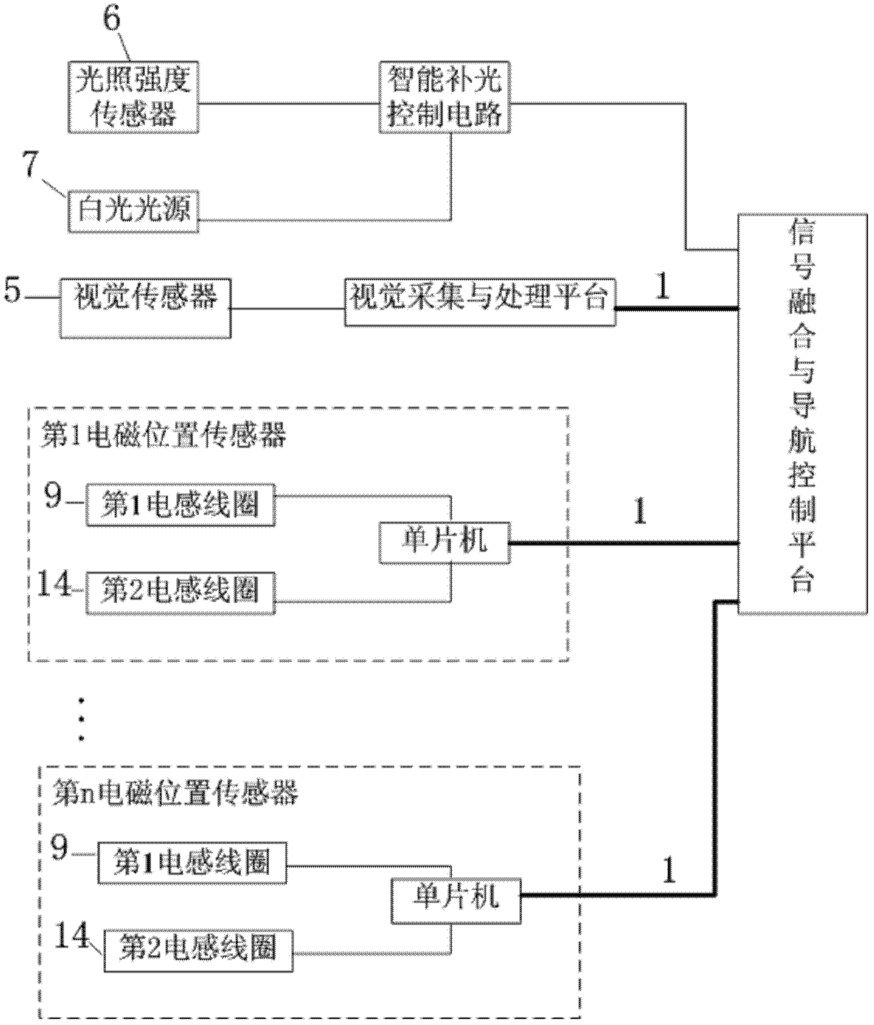
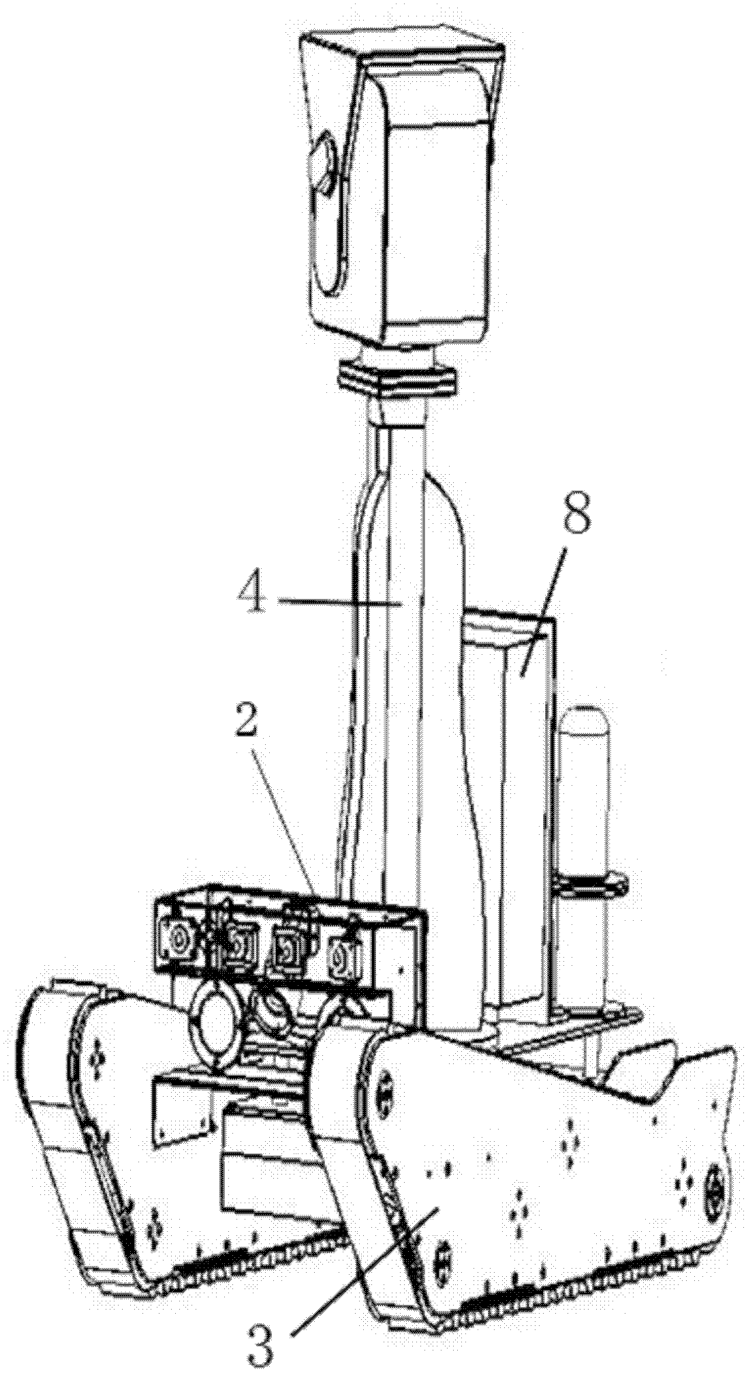
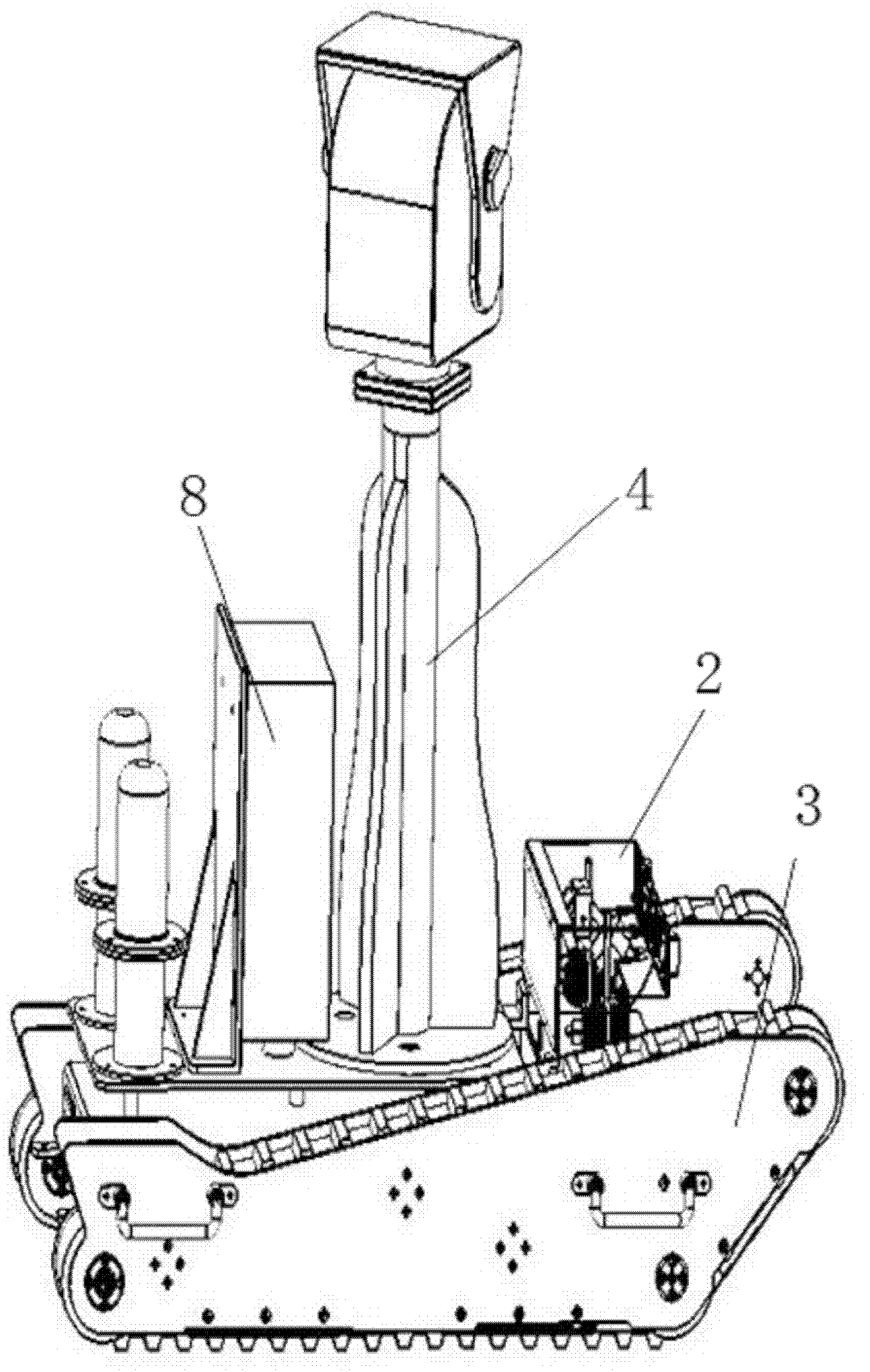
[0036] Such as figure 1 As shown, the structure of the line patrol navigation control system based on vision and electromagnetic fusion is as follows: the intelligent supplementary light control circuit is respectively connected to the light intensity sensor 6, the white light source 7 and the signal fusion and navigation control platform, and the visual acquisition and processing platform is connected to the visual sensor 5 , and connect the signal fusion and navigation control platform through the RS485 bus 1, the yellow navigation line 13 is located on the road surface; the induction navigation line 12 is laid under the road surface, the induction navigation line 12 is a BV plastic copper core wire, and the two ends of the induction navigation line 12 are connected to the electromagnetic The signal generators are connected to form a path, and the electromagnetic sig...


PUM


Abstract

The invention discloses a vision and electromagnet based fusion inspecting navigation control system, which belongs to the technical field of automatic detection and control. The vision and electromagnet based fusion inspecting navigation control system is structurally characterized in that an intelligent light filling control circuit is connected with a illumination intensity sensor, a white light source and a signal fusion and navigation control platform respectively, a vision acquisition and processing platform is connected with a vision sensor and is connected with the signal fusion and navigation control platform through a RS485 bus, yellow navigation lines are laid on road surfaces, induced navigation lines are laid under the road surfaces, and two ends of the induced navigation lines are connected with electromagnetic signal generators to form a loop. The vision and electromagnet based fusion inspecting navigation control system has the advantages that (1), speed can be optimized and increased by the aid of prospective data, the system can be adaptable to all whether including rainy and snowy days all year round; (2) the vision sensor and electromagnetic position sensors can be used independently or integrally; (3) fusion can be achieved dynamically according to requirements by the aid of an intelligent software self-adaptive data fusion unit designed and developed; and (4) cost and power consumption are low.

Description

technical field [0001] The invention belongs to the technical field of automatic detection and control, and in particular relates to a vision-based and electromagnetic-based fusion line patrol navigation control system. technical background [0002] Intelligent autonomous mobile robot is a hot spot in the field of international robotics research. Navigation control is an important part of intelligent mobile robots. In recent years, due to the rapid development of computer image processing capabilities and technology and the improvement of the performance and price ratio of a large number of digital image processing equipment, coupled with the advantages of the vision subsystem with wide signal detection range and complete target information, vision sensors are used in mobile robot navigation. More and more people pay more and more attention to the application of vision and show a good development prospect, but at the same time, the vision itself needs to be applied under th...

Claims


Application Information

Patent Timeline
IPC IPC(8): G05D1/02
Inventor 王库魏玉虎管一王德龙
Owner CHINA AGRI UNIV
Learn More