Supercharge Your Innovation With Domain-Expert AI Agents!

Baffle type wind-pressure switch

A wind pressure switch and baffle-type technology, which is applied in the direction of electric switches, electrical components, circuits, etc., can solve the problems of non-maintenance, shutdown of the whole machine, action hysteresis and failure, etc., and achieve long service life, simple structure, and easy operation. reliable effect

Inactive Publication Date: 2012-08-01
河北沃尔堡采暖设备有限公司
View PDF4 Cites 4 Cited by
  • Summary
  • Abstract
  • Description
  • Claims
  • Application Information

AI Technical Summary

Problems solved by technology

This kind of wind pressure monitoring device is costly and has a high failure rate, especially in winter, because the condensed water in the flue gas will often enter the rubber hose, causing the wind measuring device to fail to detect and cause shutdown failure; the inlet of the wind pressure sampling device often hangs Carbon deposits will also cause faults in pressure measurement; because the diaphragm is made of thin rubber material, it will also cause hysteresis and failure due to aging and other reasons; because the wind pressure switch needs to be installed near the fan, the outer shell will also be deformed due to heat. Phenomena such as air leakage from the seal will cause failure and shutdown of the whole machine. Moreover, once the air pressure switch fails, it cannot be repaired and can only be replaced as a whole. It often causes a lot of inconvenience to the user due to the untimely accessories, especially in the winter heating season. It is often impossible to heat normally for many days due to waiting for accessories, which causes unspeakable difficulties to users

Method used


Image

  • Baffle type wind-pressure switch
  • Baffle type wind-pressure switch
  • Baffle type wind-pressure switch

Examples


Embodiment Construction

[0009] The present invention will be further described below in conjunction with accompanying drawing.

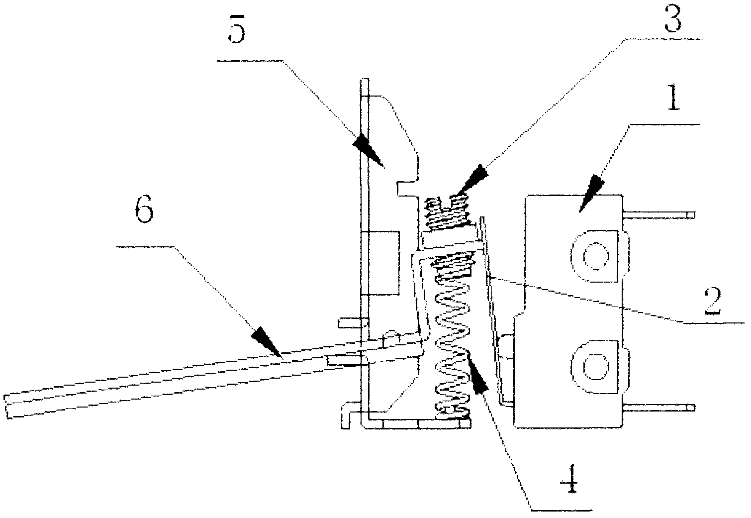
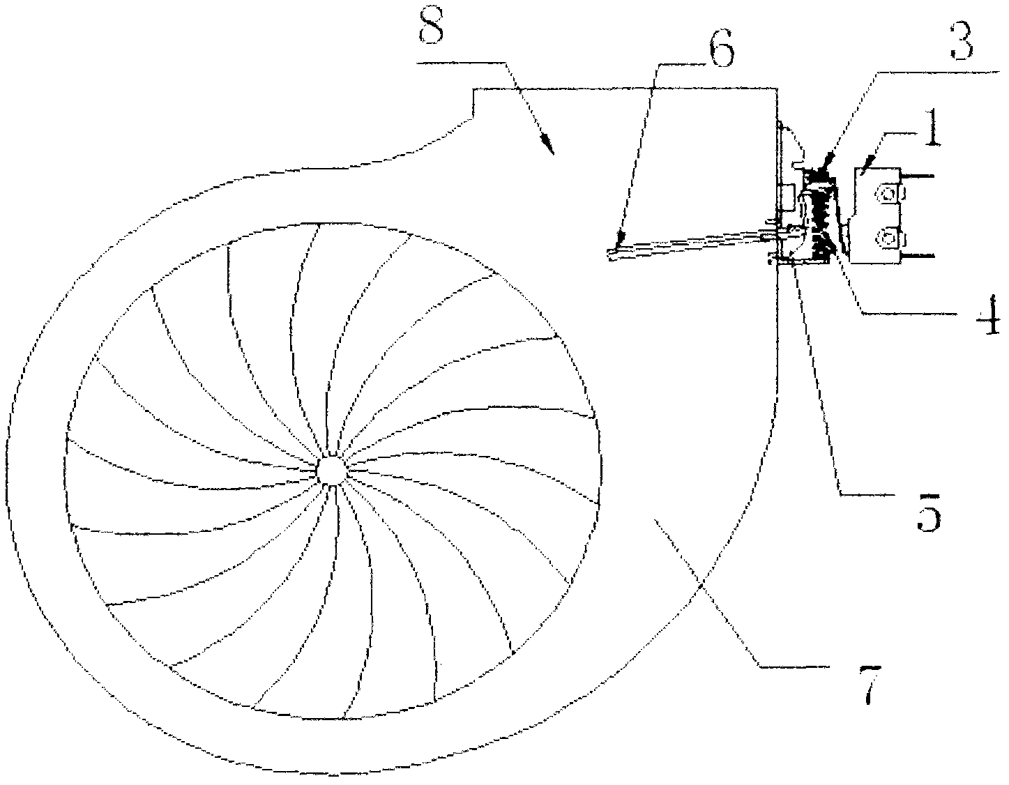
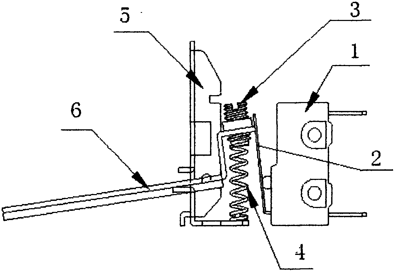
[0010] refer to figure 1 and 2 , the baffle type air pressure switch of the present invention includes a support 5, on which a wind pressure baffle 6 is hinged, and the corner plate end of the wind pressure baffle 6 is connected with a pressure regulating screw 3, and the pressure regulating screw 3 is connected to the The homing pressure-regulating spring 4 provided on the support 5 cooperates, and the contact plate 2 of the micro switch 1 contacts and cooperates with the corner extreme surface of the wind pressure baffle 6 . When in use: fix the support 5 of the baffle type air pressure switch on the side wall of the air outlet end of the fan 7, and the air pressure baffle 6 is directly inserted into the air outlet 8 of the fan from the side wall of the fan 7.

[0011] The specific implementation of the baffle-type wind pressure switch of the present invention is not li...


PUM


Abstract

The invention relates to a baffle type wind-pressure switch. The baffle type wind-pressure switch is characterized by comprising a support, wherein a wind-pressure baffle is hinged on the support; an angle plate end of the wind-pressure baffle is connected with a pressure adjusting screw which is matched with a return pressure-adjusting spring arranged on the support; and a contact plate of a microswitch is in contact matching with the angle plate end surface of the wind-pressure baffle. When in installation, the wind-pressure baffle is directly inserted into an air outlet of a fan from the side part of the fan; the wind pressure blows the wind-pressure baffle directly, so that one end of the wind-pressure baffle, which is acted by the wind pressure, is upwarped along the hinged point, while the angle plate end of the wind-pressure baffle pushes and presses down the contact plate of the microswitch, and the microswitch is switched on and outputs a wind-pressure signal; the angle plate end of the wind-pressure baffle is connected with a pressure-adjusting screw; the pressure-adjusting screw is matched with the return pressure-adjusting spring arranged on the support; and the needed control wind pressure is set by adjusting the pressure of the spring. The baffle type wind-pressure switch has the advantages of simple structure, convenience in adjustment, low cost, stable and reliable action, long service life, no influence from the use environment, no need of replacement, and the like.

Description

technical field [0001] The invention belongs to a wind pressure switch, which is a baffle type wind pressure switch. Background technique [0002] Existing gas water heaters, gas wall-hung boilers and other gas equipment equipped with fans must be installed with a set of wind pressure monitoring devices to ensure the safety of combustion. At present, the wind pressure monitoring devices on gas appliance fans are diaphragm-type structures. During installation, two rubber hoses need to be connected to the wind pressure sampling device at the outlet of the fan, and then the wind pressure transmitted by the rubber hoses pushes or pulls the diaphragm of the wind measuring device. , drive the switch installed outside the wind measuring device to output the signal. This kind of wind pressure monitoring device is costly and has a high failure rate, especially in winter, because the condensed water in the flue gas will often enter the rubber hose, causing the wind measuring device t...

Claims


Application Information

Patent Timeline
IPC IPC(8): H01H35/24
Inventor 于海智
Owner 河北沃尔堡采暖设备有限公司
Features
  • R&D
  • Intellectual Property
  • Life Sciences
  • Materials
  • Tech Scout
  • Unparalleled Data Quality
  • Higher Quality Content
  • 60% Fewer Hallucinations
Learn More