Low frequency tuning antenna applicable to explosive detection

A technology for tuning antennas and explosives, applied in discontinuous tuning with variable adjustment elements, single resonant circuits with only variable inductance/capacitance, and analysis using nuclear magnetic resonance, which can solve antenna ringing and tailing , Energy cannot be released in time, etc.

Inactive Publication Date: 2012-08-01
XIDIAN UNIV
View PDF3 Cites 13 Cited by
  • Summary
  • Abstract
  • Description
  • Claims
  • Application Information

AI Technical Summary

Problems solved by technology

[0008] When the nuclear quadrupole resonance detection system works, the transmitter and receiver in the system generally work in time-sharing. In theory, for the detection system based on FID signals, when the transmitter stops working, the receiver starts working immediately , the received NQR signal is the strongest at this time, but after the transmitter stops working, due to the high Q value of the antenna, the antenna stores a certain amount of energy, which cannot be released in time, thus forming an attenuated oscillation , that is, the ringing tail of the antenna

Method used


Image

  • Low frequency tuning antenna applicable to explosive detection
  • Low frequency tuning antenna applicable to explosive detection
  • Low frequency tuning antenna applicable to explosive detection

Examples


Embodiment 1

[0063] Embodiment 1. Shunt type low-frequency tuning antenna circuit

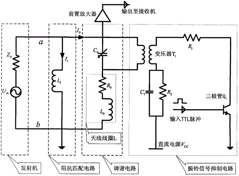
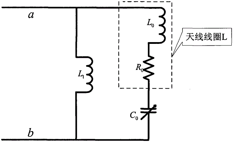
[0064] refer to figure 1 , adjustable capacitor C 0 , antenna coil L (resistor R 0 and coil L 0 in series) to form a high-Q tuned circuit, the coil L 1 That is, the impedance matching circuit is used to make the complex impedance of the tuning circuit become 50 ohms, the phase is 0, and the transformer T 1 , resistance R 1 and R 2 , capacitance C 1 , DC power supply V CC , Transistor Q 1 Constitute the ringing signal suppression circuit.

[0065] The working principle of this circuit is: the TTL pulse in the figure is controlled by computer programming. In the transmitting stage, the TTL pulse in the ringing signal suppression circuit is at low level, and the transistor Q 1 Non-conductive, the high-Q tuning circuit receives the RF pulse output from the high-power transmitter containing the characteristic frequency of the sample to be tested. The two ends of the transformer secondary are equivalent...

Embodiment 2

[0112] Embodiment 2 Voltage-dividing low-frequency tuning antenna circuit

[0113] refer to Figure 10 , adjustable capacitor C 2 , antenna coil L3 (resistor R 3 and coil L 3 series) to form a high-Q tuned circuit, the capacitor C 4 That is, the purpose of the impedance matching circuit is to make the complex impedance of the high-Q tuned circuit become 50 ohms, the phase is 0, and the transformer T2 , resistance R 4 and R 5 , capacitance C 3 , DC power supply V dd , Transistor Q 2 Constitute the ringing signal suppression circuit.

[0114] The working principle of this circuit is: the TTL pulse is controlled by computer programming. In the transmission stage, the TTL pulse in the ringing signal suppression circuit is at low level, and the transistor Q 2 Non-conductive, the high-Q tuning circuit receives the RF pulse output from the high-power transmitter containing the characteristic frequency of the sample to be tested. The two ends of the transformer secondary are ...


PUM

PropertyMeasurementUnit
internal resistanceaaaaaaaaaa
inductanceaaaaaaaaaa
q valueaaaaaaaaaa

Abstract

The invention discloses a low frequency tuning antenna applicable to explosive detection, which comprises a high Q-value tuning circuit, an impedance matching circuit and a ringing signal suppression circuit. The high Q-value tuning circuit receives radio frequency pulse containing characteristic frequency of a sample to be tested and output from a high-power transmitter. The impedance matching circuit is used for turning complex impedance of the high Q-value tuning circuit into 50 ohm, and a phase is 0. The ringing signal suppression circuit has effects that when the transmitter works, Q value of the circuit is high, and the antenna ringing signal suppression circuit does not work; and when the transmitter stops working, the Q value of the circuit is low, and residual energy stored in an antenna coil is consumed as soon as possible through the antenna ringing signal suppression circuit. Therefore, time from closing the transmitter to opening a receiver is shortened, the Q value of the circuit is high during a nuclear quadrupole resonance (NQR) signal receiving period, and detecting sensitivity on weak NQR signals is improved, namely a process that the Q value of a resonance circuit becomes smaller then bigger in a detection process is required.

Description

technical field [0001] The invention belongs to the field of radio frequency circuit design, in particular to a low-frequency tuning antenna suitable for explosive detection. Background technique [0002] The explosives detection system based on Nuclear Quadrupole Resonance (Nuclear Quadrupole Resonance abbreviated as NQR) consists of a main control computer, a signal generator, a high-power transmitter, an antenna coil, a preamplifier and a receiving device. [0003] The NQR detection process has the following steps. First, the computer sends a pulse control sequence to the signal generator, and then the signal generator generates a radio frequency pulse with the same characteristic frequency as the sample to be tested. This pulse is amplified by a high-power transmitter and sent to the antenna coil. , the antenna coil radiates an electromagnetic field outward, and the N atoms in the explosive whose nuclear quadrupole moment is not zero produce energy level transitions afte...

Claims


Application Information

Patent Timeline
Patent Type & Authority Applications(China)
IPC IPC(8): H04B1/18H03J3/20H03J5/02H03H7/38G01N24/08
Inventor 何学辉阳燕朱凯然苏涛刘宏伟
Owner XIDIAN UNIV
Why Eureka
Try Eureka