Immersion cooling conductive cross arm

A conductive cross-arm and cross-arm technology, applied in electric heating devices, electrical components, heating by discharge, etc., can solve the problems of aluminum's electrical conductivity not as good as copper's, increase processing and manufacturing costs, and complex processing techniques, and achieve a conductive area. Increase, reduce processing cost, overcome the effect of complex structure

Inactive Publication Date: 2014-09-17
宝鸡市晋旺达机械设备有限公司
View PDF4 Cites 0 Cited by
  • Summary
  • Abstract
  • Description
  • Claims
  • Application Information

AI Technical Summary

Problems solved by technology

However, the melting point of aluminum is low, and the top of the cross arm is greatly affected by high-temperature flames and thermal radiation, and the electrical conductivity of aluminum is substantially inferior to that of copper. In order to improve electrical conductivity and ensure work stability, it is necessary to use thicker At the same time, in order to improve the strength, the interior is equipped with reinforcing ribs, and the processing technology of aluminum is more complicated than that of steel and copper, which usually requires the use of special welding processing equipment, and in order to prevent the all-aluminum alloy conductive cross arm from being corroded by cooling water, Magnesium alloy materials need to be used for electrochemical anti-corrosion to improve the corrosion resistance of the plates. The anti-corrosion materials are replaced every 3 to 5 years, which not only directly increases the processing and manufacturing costs, but also leaves many problems for subsequent maintenance.

Method used


Image

  • Immersion cooling conductive cross arm
  • Immersion cooling conductive cross arm
  • Immersion cooling conductive cross arm

Examples


Embodiment 1

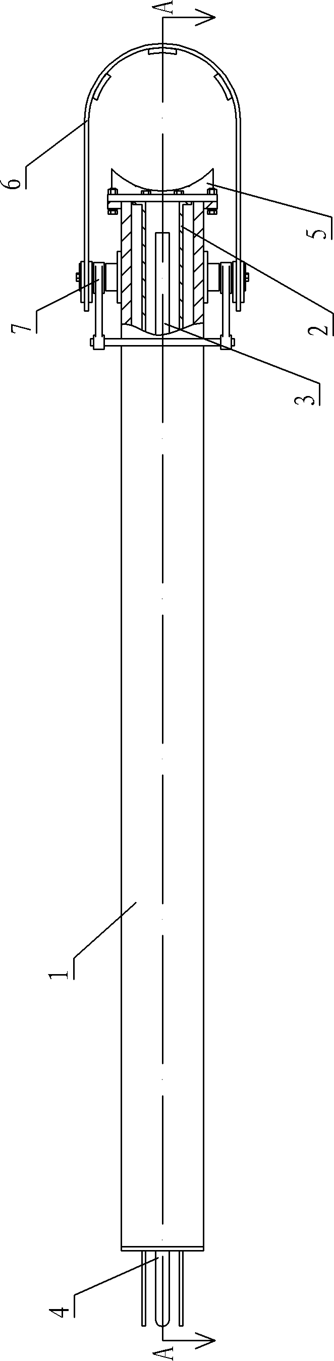
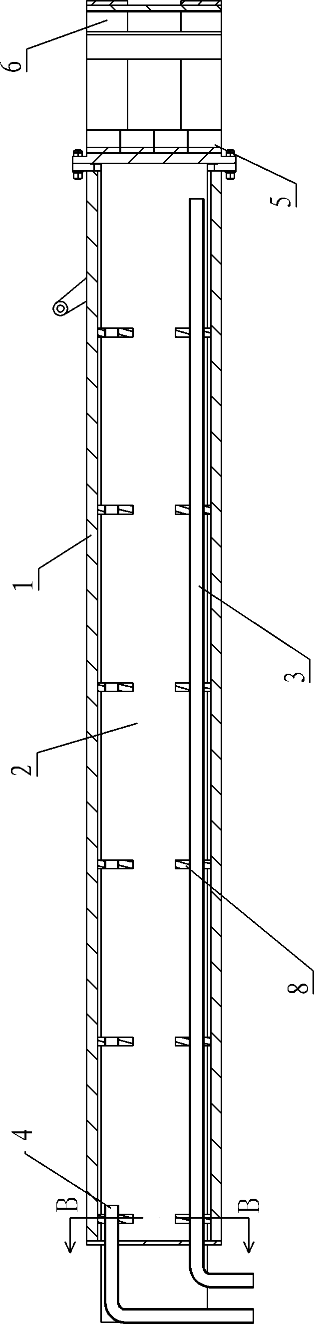
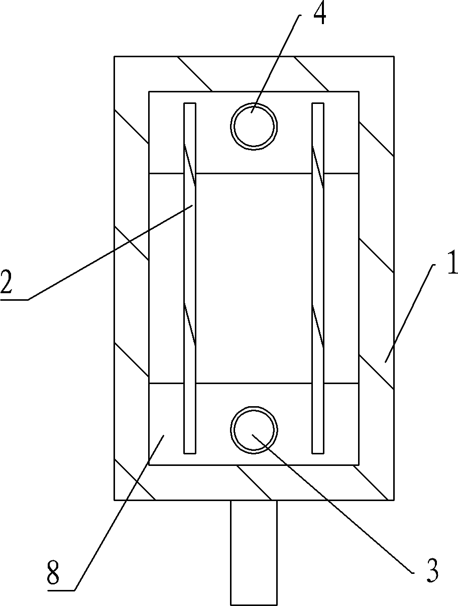
[0021] Such as figure 1 , figure 2 , image 3 and Figure 4 As shown, the immersion-type conductive cross arm of this embodiment includes a steel cross arm main body 1, a conductive copper bar 2, a water inlet pipe 3, a water outlet pipe 4, a conductive chuck 5, an electrode hoop 6, a cam locking mechanism 7, Install fixture 8. The conductive cross arm is installed on the support column through threaded fasteners and a support plate made of insulating material, and rises and falls together with the support column.

[0022] The cross arm main body 1 of the present invention is welded and processed into a rectangular box-type structure, and a copper conductive chuck 5 is installed on the front end of the cross arm main body 1 through bolts and flanges, and the electrode hoop 6 is installed on the cross arm through a cam locking mechanism 7 The front part of the arm main body 1 and the electrode hoop 6 are made of stainless steel. The electrodes (not shown) are fixed on the...


PUM


Abstract

The invention relates to an immersion cooling conductive cross arm which comprises a cross arm main body, a conductive chuck, an electrode hoop, a water inlet pipe, a water outlet pipe and a conductive copper bar, wherein the conductive chuck and the electrode hoop are arranged at the front end of the cross arm main body; an electrode is fixed on the conductive cross arm by the conductive chuck and the electrode hoop; the water inlet pipe is used for filling cooling water into the cross arm main body; the water outlet pipe is used for draining the circulating cooling water out of the cross arm main body; the conductive copper bar is arranged in the cross arm main body by a installing and fixing part; the conductive copper bar extends into the cross arm main body from the rear part of the cross arm main body; the front end of the conductive copper bar is connected with the conductive chuck; and the water outlet pipe is positioned above the water inlet pipe. According to the invention, the conductive copper bar is soaked in the cooling water and the circulation of the cooling water is carried out by utilizing the specific gravity difference of water at different temperatures so as to cool the conductive copper bar; a cooling water inlet passage and a cooling water return passage do not need to be additionally processed; and the immersion cooling conductive cross arm has simple structure and good cooling effect.

Description

technical field [0001] The invention belongs to the technical field of metallurgical equipment, and in particular relates to a conductive cross arm used on an industrial electric furnace heated by an electric arc. Background technique [0002] As a key part of the electric arc furnace, the conductive cross arm plays the role of supporting and clamping the electrodes, and conducts the electric energy from the secondary short network of the transformer to the furnace shell through the electrodes, and generates a strong arc current in the charge to heat up the melted material . The conductive cross arm is usually installed on the supporting column, and its front end clamps the electrode through the electrode clamp, so that the electrode can be accurately kept at the position of the electrode center circle during the lifting process. The lighter the weight of the conductive cross arm, the smaller the driving force for the lifting adjustment of the supporting column, and the sma...

Claims


Application Information

Patent Timeline
Patent Type & Authority Patents(China)
IPC IPC(8): H05B7/103H05B7/12
Inventor 关越张国庆李真郭云奇杨自强冯法选王鑫
Owner 宝鸡市晋旺达机械设备有限公司
Why Eureka
Try Eureka