Distorted Dammann grating and system for simultaneously imaging multiple object planes

A technology of Damman grating and imaging system, applied in diffraction grating, optics, optical components, etc., can solve problems such as uneven energy distribution

Active Publication Date: 2012-08-08
SHANGHAI INST OF OPTICS & FINE MECHANICS CHINESE ACAD OF SCI
View PDF2 Cites 14 Cited by
  • Summary
  • Abstract
  • Description
  • Claims
  • Application Information

AI Technical Summary

Problems solved by technology

The twisted Damman grating well solves the problem of unev

Method used


Image

  • Distorted Dammann grating and system for simultaneously imaging multiple object planes
  • Distorted Dammann grating and system for simultaneously imaging multiple object planes
  • Distorted Dammann grating and system for simultaneously imaging multiple object planes

Examples


Embodiment Construction

[0026] 1. Theoretical design

[0027] 1. Design of twisted Damman grating

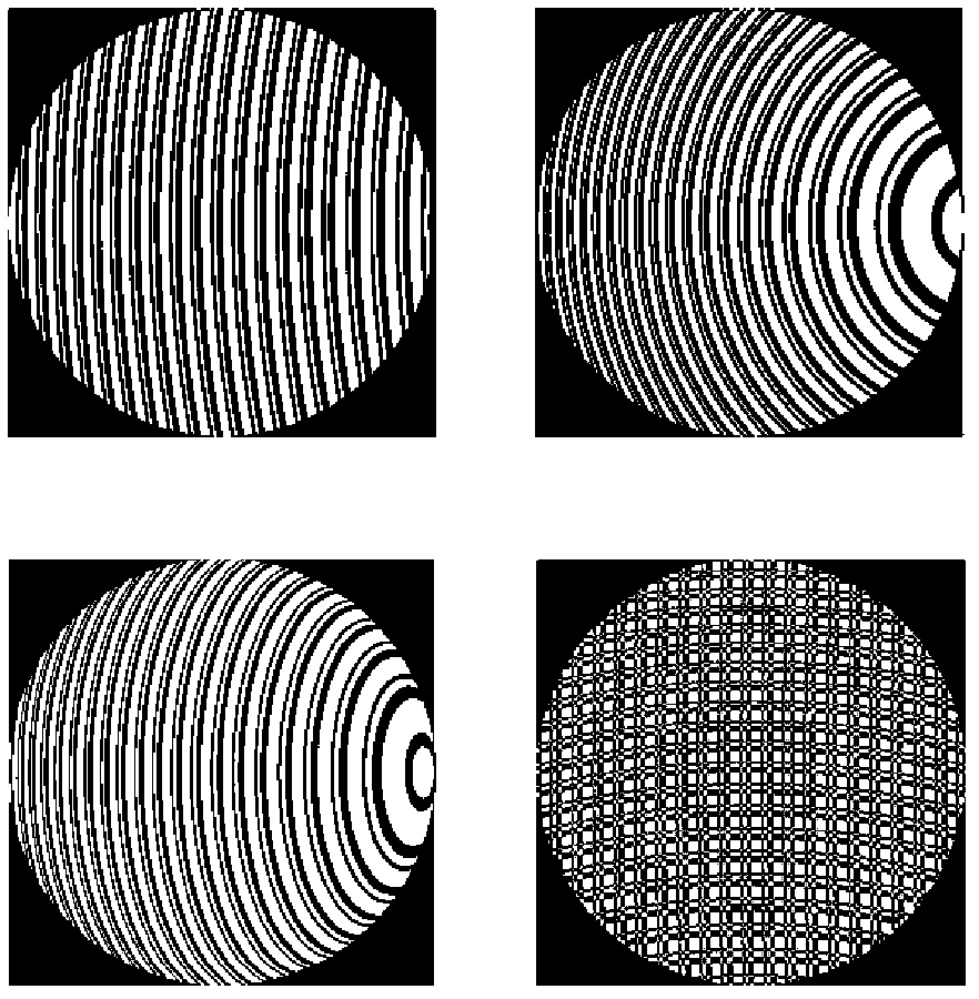
[0028] The twisted Damman grating proposed by the present invention introduces the idea of ​​Damman coding into the twisted Damman grating. Essentially, this twisted Damman grating is a computer hologram. Its transmittance function can be expressed as

[0029]

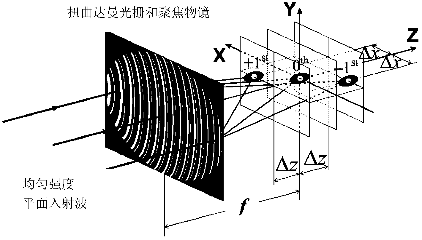
[0030] Among them, (x, y) is the Cartesian coordinate system on the normalized entrance pupil plane. α=arcsin(NA / n 0 ) is the maximum aperture angle, where NA is the numerical aperture of the focusing objective lens, n 0 is the refractive index of the objective lens back field. W 20 is the defocus factor, which represents the base defocus amount corresponding to the zero-order diffraction order. Λ 0 is the grating period along the transverse direction at the center of the twisted Damman grating aperture. C m is the coefficient corresponding to the mth diffraction order, which can be written as:

[0031] C ...


PUM


Abstract

The invention discloses a distorted Dammann grating and a system for simultaneously imaging multiple object planes. The system for simultaneously imaging multiple object planes which consists of a distorted Dammann grating and a focusing lens can be used for forming a multi-focus array of multiple equal-strength focusing light spots which are deviated simultaneously along axial and transverse directions in a back field of the focusing lens. The focus quantity and focus interval of the multi-focus system can be adjusted by changing the parameters of the distorted Dammann grating. An equal-strength multi-focus system can be used for imaging a plurality of axial planes of an object space in the same image plane. According to the system, a real-time three-dimensional imaging technology which does not require axial scanning can be realized. The real-time three-dimensional imaging technology has an important practical value in three-dimensional real-time monitoring of biological living body cell microscopy and fluid particles.

Description

technical field [0001] The invention relates to a diffractive optical element, in particular to a twisted Damman grating and a multi-object plane simultaneous imaging system. Background technique [0002] Optical imaging and optical detection technology is a non-destructive imaging and detection technology, which has important applications in biological living cell imaging. Traditional optical imaging techniques mainly include confocal microscopy, fluorescence microscopy, and optical coherence tomography. These traditional three-dimensional optical imaging technologies are generally based on point-to-point scanning or axial scanning, so they have application limitations in real-time imaging and monitoring, especially the three-dimensional real-time monitoring of living cells or particles in some fluids. [0003] In 1999, Blanchard et al. [Appl.Opt.38, 6692 (1999)] proposed a simultaneous imaging technology for multiple axial object planes based on twisted gratings, and this...

Claims


Application Information

Patent Timeline
IPC IPC(8): G02B5/18G02B27/00
Inventor 周常河余俊杰贾伟麻健勇王少卿曹红超
Owner SHANGHAI INST OF OPTICS & FINE MECHANICS CHINESE ACAD OF SCI
Why Eureka
Try Eureka