
Milling tool for gear milling

A milling tool and milling technology, applied in the direction of gear cutting tools, gear tooth manufacturing tools, milling cutters, etc., to achieve the effect of long service life and improved flexibility of use

Active Publication Date: 2012-08-15
SANDVIK INTELLECTUAL PROPERTY AB
View PDF8 Cites 12 Cited by
  • Summary
  • Abstract
  • Description
  • Claims
  • Application Information

AI Technical Summary

Problems solved by technology

The disadvantage of this type of milling tool is that it requires at least twice as many milling inserts, two for each cut

Method used


Image

  • Milling tool for gear milling
  • Milling tool for gear milling
  • Milling tool for gear milling

Examples


Embodiment Construction

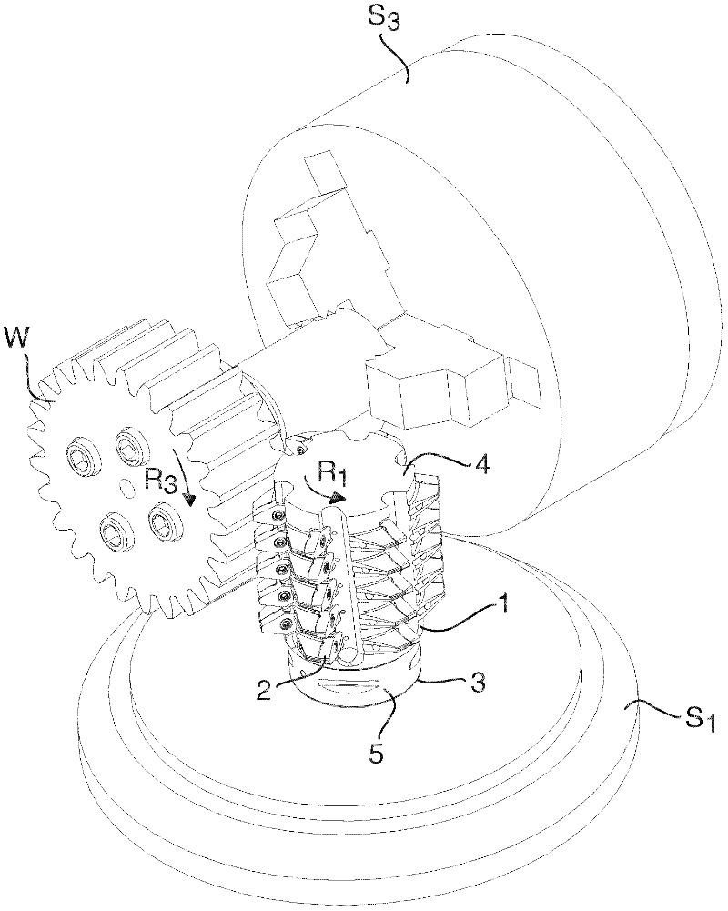
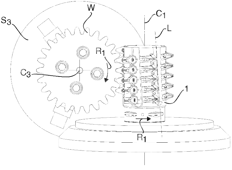
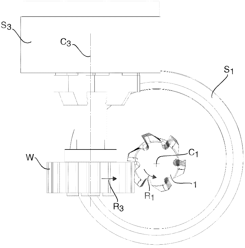
[0044] Figure 1-9 An embodiment of a milling tool formed for gear cutting and more particularly for so-called hobbing of toothed workpieces W is shown. Milling tools are suitable for cutting machining of different workpieces W such as gears, racks, splines, impellers for hydraulic pumps and similar cogged elements.

[0045] The milling tool comprises a tool body 1 and a large number of replaceable milling inserts 2 . The milling insert 2 is made of a material harder than the tool body 1 , such as cemented carbide. The tool body 1 can be manufactured from steel.

[0046] The tool body 1 defines an axis of rotation C 1 And has a fixed end 3 and an opposite outer end 4. Axis of rotation C 1 Extends through the fixed end 3 and the outer end 4 . On the fixed end 3 there is a fastening pin 5, see Figure 5 , for securing the tool body 1 and the milling tool to the tool spindle S of the milling cutter or multi-operation machine tool 1 middle. The tool body 1 revolves around...


PUM


Abstract

A milling tool, for the hobbing of a workpiece having cogs, comprises a tool body (1) that has a fixing end (3), an opposite outer end (4), and a peripheral surface (7). The tool body comprises a large number of separated seats (9) that are arranged at the peripheral surface (7) one after the other along a helix line (x) having a constant pitch. A corresponding large number of replaceable milling inserts (2) comprise an under side (21), an opposite upper side (22) that forms a chip surface (24), a circumferential edge side (23), two pairs of main cutting edges (25). The chip surface (24) extends in an extension plane that comprises the main cutting edges. Each seat is formed to receive one of the milling inserts and comprises a support surface that allows support to the milling insert projecting from the tool body for cutting engagement with a gash of the workpiece. The chip surface extension plane of each milling insert has a normal that is parallel to the tangent of the helix line where the same intersects the extension plane.

Description

technical field [0001] The invention relates to milling tools for gear milling and more particularly for so-called hobbing. More specifically, the invention relates to a milling tool according to the preamble of claim 1, see US-A-5,593,254. Background technique [0002] Milling tools are provided for gear milling of gears of different modules Mn depending on the size of the gear to be produced. There are modules ranging from Mn = 1 for very small gears to Mn = 22 or more for very large gears. The tool according to the invention can be used for gears of all modules and is especially suitable for milling gears with Mn=3 to Mn=8. [0003] US-A-5,593,254 shows a milling tool formed for hobbing toothed workpieces such as gears, racks and the like. The milling tool comprises a tool body defining an axis of rotation and having a fixed end, an opposite outer end and a peripheral surface extending around the axis of rotation between the fixed end and the outer end. The tool body ...

Claims


Application Information

Patent Timeline
IPC IPC(8): B23F21/16
CPCB23F21/166Y10T407/1725B23F1/06B23F21/126B23F21/163
Inventor 斯图雷·舍马茨·温莫
Owner SANDVIK INTELLECTUAL PROPERTY AB
Learn More