High-speed spindle for spinning frame

A spinning frame, high-speed technology, used in textiles and papermaking, etc., can solve the problems of lubricating oil not circulating, low dynamic pressure oil film bearing capacity, affecting the service life of spindles, etc., to prevent overheating and shaft holding, high-speed stability. , the effect of low power consumption

Active Publication Date: 2012-08-15
TONGXIN TEXTILE MACHINERY WUHU
View PDF9 Cites 7 Cited by
  • Summary
  • Abstract
  • Description
  • Claims
  • Application Information

AI Technical Summary

Problems solved by technology

[0004] However, this kind of flat bottom structure spindle also has defects. Since the flat bottom type spindle is a single oil wedge fixed pad type dynamic pressure bearing, the dynamic pressure oil film generated by the bearing has a small bearing capacity and low centering accuracy; at the same time, the spindle bar and the lower bearing The lubricating oil between the spindles cannot circulate and flow, the lubricating oil is heated repeatedly, the temperature of the lower bearing rises, and the lower bearing of the spindle is prone to overheating and shaft locking; the upper bearing is lubricated by the centrifugal force of the spindle when it rotates at high speed to produce mist lubrication. When the oil level is low, the lubrication condition of the upper bearing becomes poor, and it is easy to wear, which affects the service life of the spindle

Method used


Image

  • High-speed spindle for spinning frame
  • High-speed spindle for spinning frame
  • High-speed spindle for spinning frame

Examples


Embodiment Construction

[0027] The specific implementation manner of the present invention will be described in further detail below by describing the best embodiment with reference to the accompanying drawings.

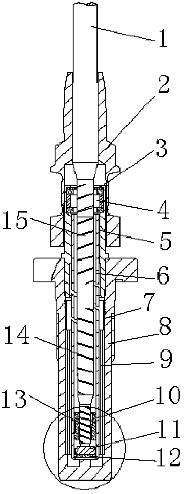
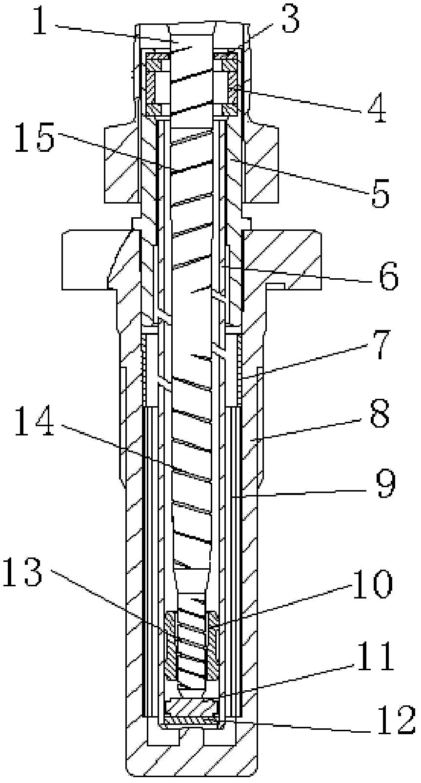
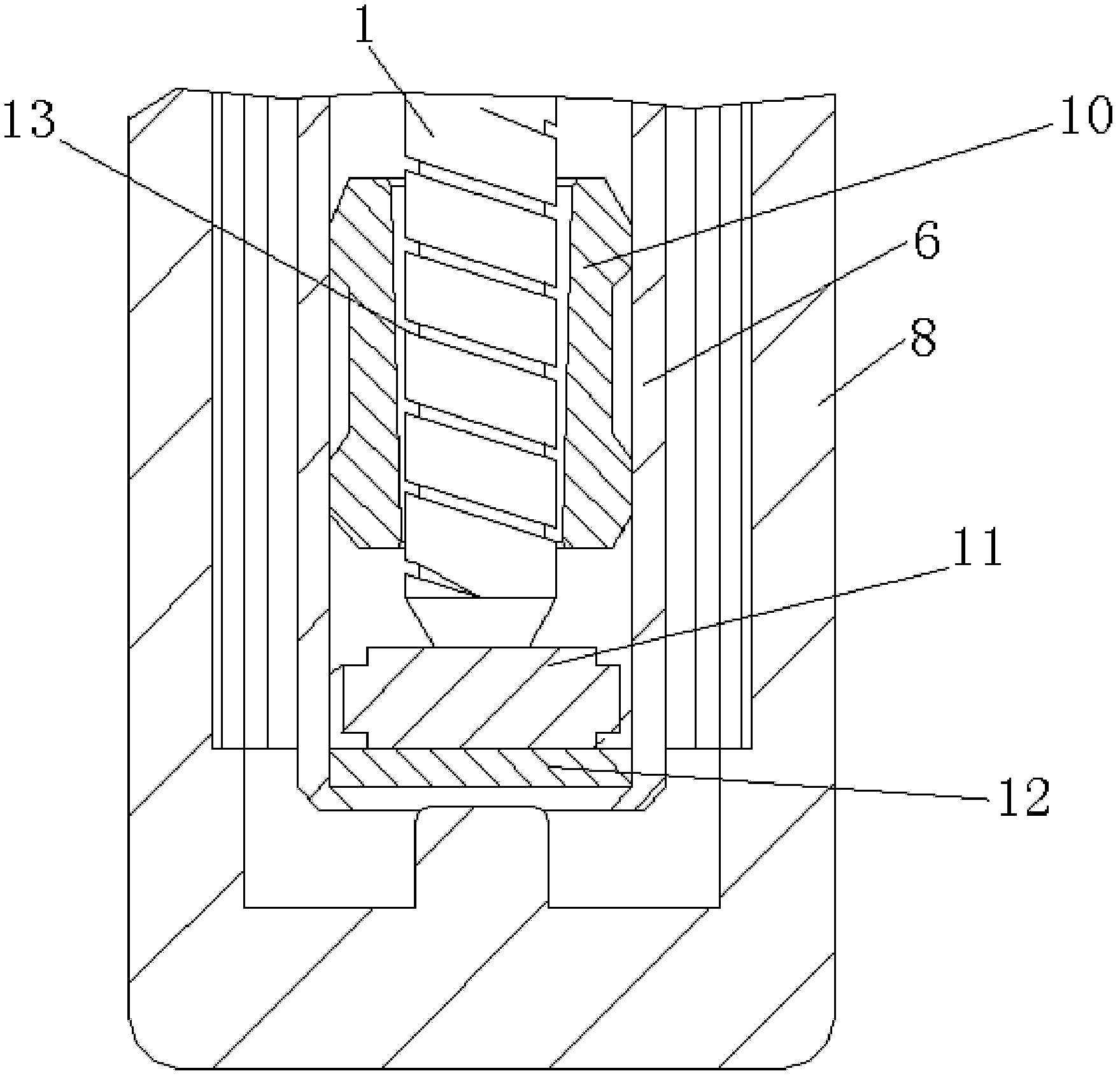
[0028] Such as figure 1 and figure 2 As shown, the high-speed spindle for the spinning frame includes a spindle bar 1, an upper bearing 4 is arranged on the top of the spindle bar 1, and a bearing seat 5 is set outside the upper bearing 4; a spindle disc 2 is set on the spindle bar 1, and the One end of the bearing seat 5 on the upper bearing 4 penetrates into the interior of the spindle disc 2; the lower part of the spindle rod 1 is fitted with an elastic tube 6, and one end of the elastic tube 6 penetrates into the other end of the bearing seat 5; 8. The upper end is connected to the other end of the bearing seat 5; a lower bearing 10 is provided at the lower end of the spindle bar 1 located in the elastic tube 6; a helical groove is provided on the surface of the spindle bar 1, and th...


PUM


Abstract

The invention discloses a high-speed spindle for a spinning frame. The high-speed spindle comprises a spindle blade, wherein an upper bearing is arranged at the upper part of the spindle blade and a bearing seat is arranged outside the upper bearing; an elastic tube is arranged at the lower part of the spindle blade; a lower bearing is arranged at the lower end of the spindle blade in the elastic tube; spiral linear grooves are formed on the surface of the spindle blade and comprise a first spiral linear groove, a second spiral linear groove and a third spiral linear groove; the first spiral linear groove is arranged at the lower part on which the lower bearing is arranged, of the spindle blade; the third spiral linear groove is arranged at the upper par on which the upper bearing is arranged, of the spindle blade; and the second spiral linear groove is arranged between the first spiral linear groove and the second spiral linear groove on the spindle blade. The high-speed spindle for the spinning frame is strong in bearing capacity, high in centering precision and good in high-speed stability, and the service life of the spindle can be prolonged effectively.

Description

technical field [0001] The invention relates to the field of textile machinery, in particular to a high-speed spindle for spinning frames. Background technique [0002] The spindle is one of the main components of twisting and winding on the spinning frame, and it is an assembly with a slender rotary shaft supported by two points as the main body. my country is a big textile country. At present, 95% of the spindles used in the spinning frame are the traditional conical spindle bottom structure spindles. The conical spindle bottom structure spindles are prone to axial movement during operation, and the spindle rod deviates from the center position to cause low-frequency vibration. Poor high-speed stability and other problems, the spindle speed can only be below 18000r / min, and the efficiency is low; and because the flat spindle bottom structure hydrodynamic pressure sliding bearing spindle can reach a maximum spindle speed of 25000r / min, with the advantages of high speed and e...

Claims


Application Information

Patent Timeline
Patent Type & Authority Applications(China)
IPC IPC(8): D01H7/04D01H7/12D01H7/20
Inventor 陆惠文刘滔李斌
Owner TONGXIN TEXTILE MACHINERY WUHU
Why Eureka
Try Eureka