Water feeding system for multiple condensing boilers

A water supply system, condensing technology, applied in the field of water supply system of multiple condensing boilers, can solve the problems of water shortage, affecting the efficiency of economizer, affecting the work of economizer, etc., and achieve the effect of high thermal efficiency

Active Publication Date: 2014-03-26
CHINA TOBACCO ZHEJIANG IND
View PDF6 Cites 0 Cited by
  • Summary
  • Abstract
  • Description
  • Claims
  • Application Information

AI Technical Summary

Problems solved by technology

[0008] 1. Due to the different equipment and pipeline resistance between the condensing economizers of each boiler, the hydraulic power of the water supply system is unbalanced, and the economizers with less water intake cannot operate efficiently;
[0009] 2. The condensing economizer of the boiler that is not in use is also inflowing water at the same time, which will cause insufficient water inflow to the condensing economizer in operation and affect the efficiency of the economizer;
[0010] 3. When the water level of the deaerator is high, if the water inlet regulating valve of the deaerator is turned down or closed, it will affect the work of all economizers;
[0011] 4. Since the water demand of each boiler condensing economizer is less than the water intake of the boiler itself, if the deaerator is in the case of less return water, it will make the deaerator insufficient water and water shortage, which will affect Boiler running normally
[0014] However, the above two invention patents only involve the water supply system of a single condensing boiler, which fails to solve the problem of unbalanced water volume in different operating modes of multiple boilers, and cannot guarantee the effective water supply of each condensing economizer of the boiler in use.

Method used


Image

  • Water feeding system for multiple condensing boilers

Examples


Embodiment 1

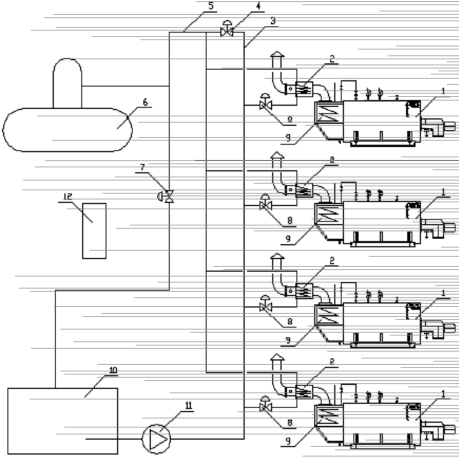
[0030] Such as figure 1 As shown, the present invention is a water supply system for multiple condensing boilers, wherein there are four condensing boilers 1, and the flue of each condensing boiler is provided with a conventional economizer 9 and a condensing economizer 2 in sequence along the flue gas flow direction. .

[0031] The water supply system includes soft water tank 10, soft water pump 11, deaerator 6, water supply main pipe 3, return water main pipe 5, bypass regulating valve 4, branch pipe regulating valve 7, water inlet regulating valve 8 and PLC control cabinet 12, and connected The way is as follows:

[0032] The outlet of the soft water tank 10 is connected to the main water supply pipe 3 through the soft water pump 11, the inlets of all condensing economizers 2 are connected in parallel to the water supply main pipe 3 through their respective water inlet regulating valves 8, and the outlets of all condensing economizers 2 are connected in parallel to the ret...


PUM


Abstract

The invention discloses a water feeding system for multiple condensing boilers. At least two condensing boilers can be used, and the condensing boilers are respectively provided with a condensing economizer, the water feeding system comprises a soft water tank, a soft water pump, a deaerator, a water supply main pipe, a water return main pipe, a bypass adjusting valve, a branch pipe adjusting valve, a water intake adjusting valve and a PLC (programmable logic controller) control cabinet, all the condensing economizers adopt the parallel main pipe type water supply mode, and the amount of water fed into each condensing economizer is controlled by the water intake adjusting valve according to the exhaust gas temperature; the water supply main pipe and the water return main pipe are communicated via the bypass adjusting valve, and the water return main pipe is also connected with an inlet of the deaerator; a branch pipe on the water return main pipe is communicated with the soft water tank through the branch pipe adjusting valve; the soft water tank is communicated with the water supply main pipe through the soft water pump; and the whole water feeding system is controlled by the PLC control cabinet. The effect of balance of water supply for different condensing boilers in different operating modes can be realized, the thermal efficiency of the boiler can be increased, the normal water level of the deaerator can be ensured, and automatic control can be realized.

Description

technical field [0001] The invention relates to a boiler water supply system, in particular to a water supply system for multiple condensing boilers. Background technique [0002] Both urban heating boilers and industrial boilers consume a large amount of primary energy and emit a large amount of pollutants at the same time. The exhaust gas temperature of traditional coal-fired heating boilers is usually higher than 150°C, and that of steam boilers is even higher than 200°C. After using natural gas, most boiler exhaust gas temperatures are between 140 and 200 °C, which consumes a lot of energy. [0003] Conventional energy-saving methods for traditional boiler water supply systems are: soft water tank→soft water pump→deaerator→boiler feed water pump→boiler conventional economizer→boiler, most of the sensible heat in the flue gas is transferred to water or steam, and the feed water can be changed from 103℃ When heated to about 135°C, the exhaust gas temperature drops from 2...

Claims


Application Information

Patent Timeline
Patent Type & Authority Patents(China)
IPC IPC(8): F22D1/50
Inventor 张拥军章伟良袁根洪裘明祥
Owner CHINA TOBACCO ZHEJIANG IND
Why Eureka
Try Eureka