Method of adhering sensor chips

A sensor chip and silicon chip technology, applied in the direction of instruments, measuring devices, measuring force, etc., can solve problems such as drift, easy creep of fixing glue, and inability to achieve accurate pressure measurement, so as to achieve the effect of avoiding drift and accurate measurement

Inactive Publication Date: 2012-08-15
无锡永阳电子科技有限公司
View PDF5 Cites 17 Cited by
  • Summary
  • Abstract
  • Description
  • Claims
  • Application Information

AI Technical Summary

Problems solved by technology

Although the use of fixing glue can realize the sticking of the strain gauge, the fixing glue is prone to creep after a long time, which makes the pressure signal drift from the diaphragm to the strain gauge during measurement.
Therefore, a pressure sensor made of a fixed adhesive bonded to a strain gauge cannot achieve accurate pressure measurement

Method used


Image

  • Method of adhering sensor chips
  • Method of adhering sensor chips
  • Method of adhering sensor chips

Examples


Embodiment 1

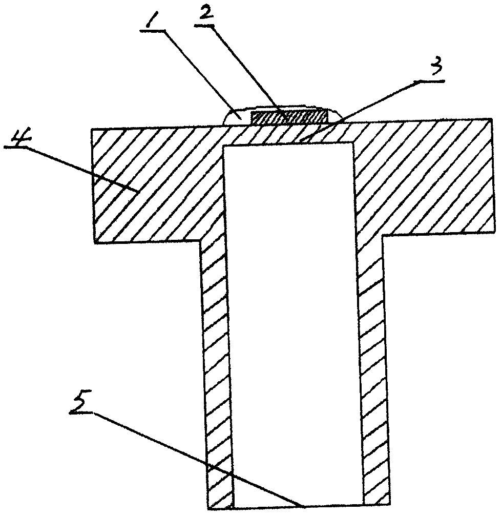
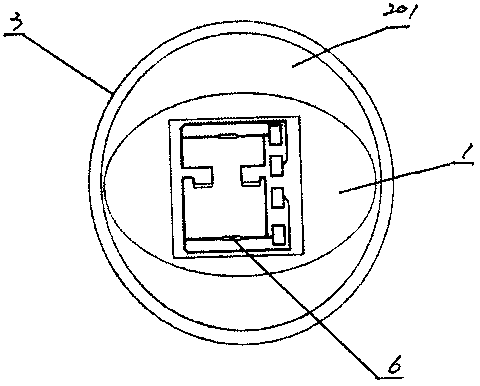
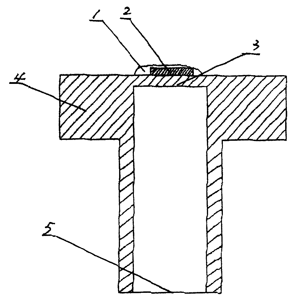
[0018] Such as figure 1 and figure 2 As shown, prepare the metal base and the sensor chip 2 first. The metal base is tubular, one end of which is processed with a back cover for constituting the metal diaphragm 3 , and the outer boss 4 is machined in the outer circle of the end with the back cover. The other end of the metal base is open to form the port 5 . The sensor chip 2 includes a silicon chip 201 on which four strain gauges 6 are integrated, and the four strain gauges are connected to form a Wheatstone bridge through metallization deposition.

[0019] Then, the metal diaphragm 3 is subjected to shot blasting treatment with a shot blasting machine, so that the outer surface of the metal diaphragm 3 forms a rough surface.

[0020] Afterwards, the glass powder is printed on the rough surface of the metal diaphragm 3 by using a screen printing machine.

[0021] Afterwards, put the metal base with the glass powder into a tube furnace at a temperature of 450°C for heatin...

Embodiment 2

[0024] Such as figure 1 and figure 2 As shown, prepare the metal base and the sensor chip 2 first. The metal base is tubular, one end of which is processed with a back cover for constituting the metal diaphragm 3 , and the outer boss 4 is machined in the outer circle of the end with the back cover. The other end of the metal base is open to form the port 5 . The sensor chip 2 includes a silicon chip 201 on which four strain gauges 6 are integrated, and the four strain gauges are connected to form a Wheatstone bridge through metallization deposition.

[0025] Then, the metal diaphragm 3 is subjected to shot blasting treatment with a shot blasting machine, so that the outer surface of the metal diaphragm 3 forms a rough surface.

[0026] Afterwards, the glass powder is printed on the rough surface of the metal diaphragm 3 by using a screen printing machine.

[0027] Afterwards, put the metal base with the glass powder in a tube furnace with a temperature of 500° C. for heat...

Embodiment 3

[0030] Such as figure 1 and figure 2 As shown, prepare the metal base and the sensor chip 2 first. The metal base is tubular, one end of which is processed with a back cover for constituting the metal diaphragm 3 , and the outer boss 4 is machined in the outer circle of the end with the back cover. The other end of the metal base is open to form the port 5 . The sensor chip 2 includes a silicon chip 201 on which four strain gauges 6 are integrated, and the four strain gauges are connected to form a Wheatstone bridge through metallization deposition.

[0031] Then, the metal diaphragm 3 is subjected to shot blasting treatment with a shot blasting machine, so that the outer surface of the metal diaphragm 3 forms a rough surface.

[0032] Afterwards, the glass powder is printed on the rough surface of the metal diaphragm 3 by using a screen printing machine.

[0033] Afterwards, putting the metal base with the glass powder into a tube furnace with a temperature of 550° C. is...


PUM


Abstract

The invention relates to a method of adhering sensor chips and in particular to a method of adhering sensor chips on metal membranes through a glass micro-fusion method. The method comprises the steps of: firstly preparing a metal pedestal and a sensor chip, wherein a sealing bottom used for forming a metal membrane is arranged on one end of the metal pedestal, and an end port is reserved on the other end of the metal pedestal, the sensor chip comprises a silicon chip, four foil gauges are integrated on the silicon chip, and the four foil gauges are connected to a Wheatstone bridge through metallization deposition; and then, processing the outer surface of the metal membrane to a rough surface; printing glass powder on the rough surface; putting the metal pedestal with the glass powder in a tubular furnace with temperature of 450-550 DEG C for heating, putting the sensor chip on the glass powder when the glass powder on the metal membrane is at a semi-fusion state, and continuing to heat to embed the sensor chip in the fused glass solution; and finally, stopping heating and naturally cooling the sensor chip.

Description

technical field [0001] The invention relates to a method for preparing a sensor chip. Specifically, it is a method of pasting the sensor chip on the metal diaphragm by using the glass micro-fusion method. Background technique [0002] It is known in the electronic field that the sensing head of the pressure sensor is composed of a metal base and a sensor chip pasted on the metal diaphragm of the metal base. The metal base is tubular, one end of which is processed with a back cover for a metal diaphragm, and the other end is left with a port. The sensor chip includes a silicon chip, and four strain gauges are integrated on the silicon chip, and the four strain gauges are connected to form a Wheatstone bridge through metallization deposition. Pressure is measured using a Wheatstone bridge. When mechanical stress is applied to the metal diaphragm, two strain gauges are stretched and the other two are compressed, making the bridge unbalanced, resulting in an output voltage th...

Claims


Application Information

Patent Timeline
Patent Type & Authority Applications(China)
IPC IPC(8): G01L1/22
Inventor 朱荣惠芦婧雯
Owner 无锡永阳电子科技有限公司
Why Eureka
Try Eureka