Voltage controlled delay chain-based time domain successive approximation digital intelligent battery current detection circuit and realizing method thereof

A technology of current detection circuit and voltage control delay, applied in the direction of measuring current/voltage, measuring device, measuring electrical variables, etc., can solve the problems of difficult process realization and low speed of detection circuit, so as to reduce the difficulty of realization and improve the conversion. The effect of precision and conversion speed

Inactive Publication Date: 2012-08-15
HARBIN INST OF TECH
View PDF4 Cites 10 Cited by
  • Summary
  • Abstract
  • Description
  • Claims
  • Application Information

AI Technical Summary

Problems solved by technology

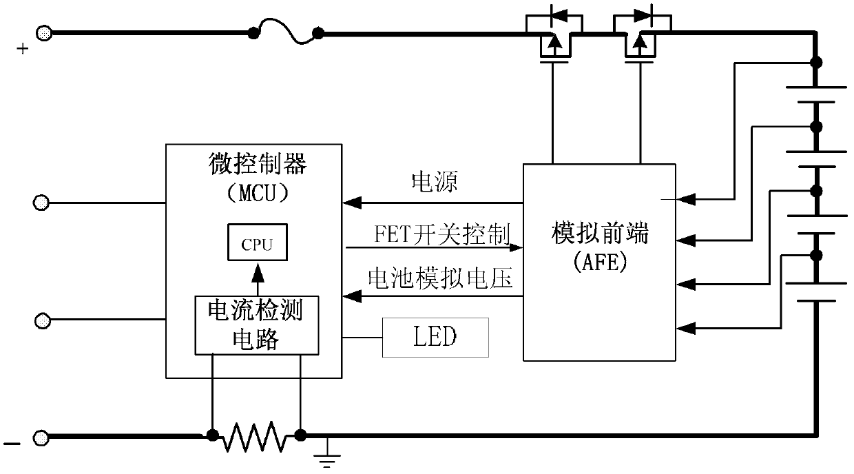
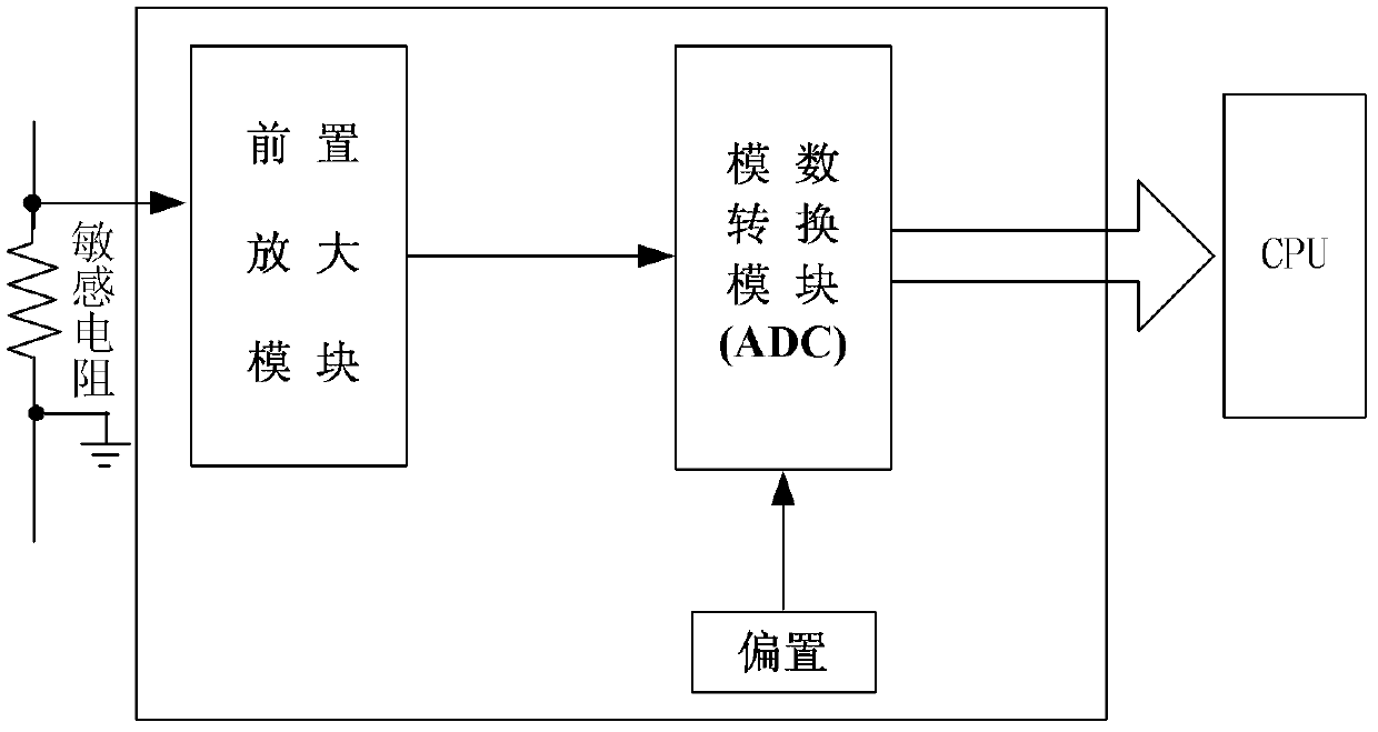
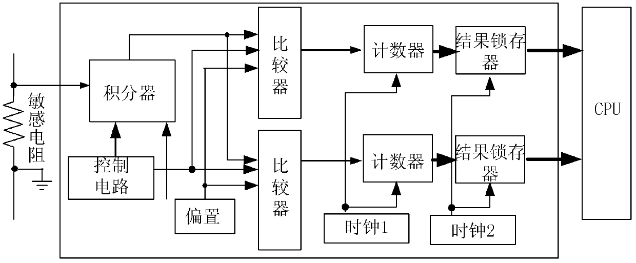
[0006] The present invention aims to solve the problems of low detection circuit speed and difficult process realization of existing intelligent batteries and battery packs, and proposes a time-domain successive approximation digital intelligent battery current detection circuit based on a voltage-controlled delay chain and its implementation method

Method used


Image

  • Voltage controlled delay chain-based time domain successive approximation digital intelligent battery current detection circuit and realizing method thereof
  • Voltage controlled delay chain-based time domain successive approximation digital intelligent battery current detection circuit and realizing method thereof
  • Voltage controlled delay chain-based time domain successive approximation digital intelligent battery current detection circuit and realizing method thereof

Examples


specific Embodiment approach 1

[0012] Specific implementation mode 1. Combination Figure 5To illustrate this embodiment, the time-domain successive approximation digital smart battery current detection circuit based on the voltage-controlled delay chain includes a sensitive resistor 1, a level shift circuit 2, a charge and discharge flag judgment circuit 3, a reference and bias circuit 4, a voltage Controlled delay chain 5, adjustable voltage-controlled delay chain 6, delay adjustment circuit 7, time comparator 8, time domain successive approximation control logic circuit 9, result latch 10, clock 11 and CPU12, sensitive resistor 1 connected in series In the charge and discharge circuit of the battery, the level shift circuit 2 is used to collect the terminal voltage of the sensitive resistor 1, and the reference and bias circuit 4 outputs the first reference and bias voltage signals to the level shift circuit 2, and the level shift circuit 2 According to the reference and bias voltage signal, the input te...

specific Embodiment approach 2

[0013] Specific embodiment two, based on the implementation method of the time domain successive approximation digital smart battery current detection circuit based on the voltage-controlled delay chain, the level signal Vctrl output of the level shift circuit 2 is connected to the voltage-controlled delay chain 5 so that The delay adjustment circuit 7 outputs the pulse signal T to the voltage-controlled delay chain 5 1 Delay a voltage-related time, at the same time, delay adjustment circuit 7, adjustable voltage-controlled delay chain 6, time comparator 8 and time-domain successive approximation control logic circuit 9 form a feedback loop, using the method of successive approximation to adjust the adjustable The adjustable voltage-controlled delay pulse signal T of the voltage-controlled delay chain 6 2 output until the adjustable voltage-controlled delay pulse signal T of the adjustable voltage-controlled delay chain 6 2 Output and the voltage-controlled delay pulse signal...

specific Embodiment approach 3

[0014] Specific embodiment three, combine Figure 6 Describe this embodiment, this embodiment is a further limitation to specific embodiment 1, the voltage-controlled delay chain 5 is composed of an M-level voltage-controlled delay chain and an N-level 2-to-1 selector, and the M-level voltage-controlled The delay chain adopts a series structure, and the N-level 2-to-1 selector adopts a series structure, and the pulse signal T 1 Delay a time related to the Vctrl voltage through the M-level voltage-controlled delay chain, and then get the pulse signal T through the N-level 2-to-1 selector D , the N-level 2-to-1 selector is used to maintain symmetry with the adjustable voltage-controlled delay chain 6 .


PUM


Abstract

The invention discloses a voltage controlled delay chain-based time domain successive approximation digital intelligent battery current detection circuit and a realizing method thereof, belonging to a current detection circuit. In order to solve the problems of low speed and large process difficulty of the traditional intelligent battery detection circuit, the voltage controlled delay chain-based time domain successive approximation digital intelligent battery current detection circuit comprises a sensitive resistor, a level shift circuit, a charge and discharge mark decision circuit, a reference and biasing circuit, a voltage controlled delay chain, an adjustable voltage controlled delay chain, a delay regulation circuit, a time comparer, a time domain successive approximation control logic circuit, a result latch, a clock and a CPU (central processing unit). The realizing method comprises the following steps that: a level signal of the level shift circuit outputs to the voltage controlled delay chain to ensure that an output signal T1 delays one time relevant to the voltage; the delay regulation circuit, the adjustable voltage controlled delay chain, the time comparer and the time domain successive approximation control logic circuit form a feedback circuit, the output of a signal T2 of the adjustable voltage controlled delay chain is regulated until the T2 and the T1 are kept consistent; and the time domain successive approximation control logic circuit latches the output of a digital signal down. The realizing method is used in the intelligent battery current detection circuit.

Description

technical field [0001] The invention belongs to the field of current detection circuits, and relates to a current detection circuit used in intelligent control circuits for the protection and measurement of intelligent batteries and battery packs in the form of a microcontroller. Background technique [0002] In recent years, the rapid development of portable electronic products has promoted the upgrading of battery technology. Nickel-chromium batteries, nickel-metal hydride batteries and ordinary disposable batteries can no longer meet the increasing demands in terms of weight, volume, energy ratio and recyclable charge and discharge utilization. The power requirements of modern portable devices. Especially recently, the miniaturization and weight reduction of electronic products represented by mobile phones and the high performance of rechargeable batteries represented by smart batteries used in notebook computers have placed higher demands on batteries. [0003] Recharge...

Claims


Application Information

Patent Timeline
Patent Type & Authority Applications(China)
IPC IPC(8): G01R19/257
Inventor 王永生喻明艳宗士新
Owner HARBIN INST OF TECH
Why Eureka
Try Eureka