Error counter for electric energy meter and error counting method

A technology for electric energy meters and calculators, applied in the hardware field of electric energy meter error calculators, can solve problems such as abnormal operation, error calculator crashes, and increased troublesome settings, so as to reduce the amount of settings, increase software protection processing, and avoid setting parameters mutual confusion effect

Active Publication Date: 2012-08-15
ELECTRIC POWER RESEARCH INSTITUTE OF STATE GRID SHANDONG ELECTRIC POWER COMPANY +1
View PDF5 Cites 3 Cited by
  • Summary
  • Abstract
  • Description
  • Claims
  • Application Information

AI Technical Summary

Problems solved by technology

[0002] The traditional error calculation method is to classify the types of pulses connected to the calibration meter, whether to access high-frequency pulses or low-frequency pulses. This work must be solved before calibration. If in If there is no processing before the calibration, the traditional error calculator may crash or work abnormally; secondly, according to the traditional error calculation metho...

Method used


Image

  • Error counter for electric energy meter and error counting method
  • Error counter for electric energy meter and error counting method
  • Error counter for electric energy meter and error counting method

Examples


Embodiment 1

[0066] Image 6 Among them, the watt-hour meter error calculator of this embodiment adopts a high-precision, high-stability 10M constant temperature crystal oscillator as the filling pulse of pulse modulation, and is respectively connected to the T2 and T3 counters of the single-chip microcomputer after 100 frequency division and 5 frequency division, wherein T2 The counter is connected with 100KHz pulse, the standard crystal oscillator pulse is used for internal counting of the time control quantity, the T3 counter is connected with 2MHz pulse, the standard crystal oscillator pulse is used as the filling pulse of pulse modulation, and the calibration pulse CLK is connected to the T0 counter and T0 capture interrupt of the single chip microcomputer , the standard meter pulse FH is connected to the T1 counter and T1 capture interrupt of the single-chip microcomputer, and the data calculated by the single-chip microcomputer is transmitted to the computer through the RS232 serial ...

Embodiment 2

[0070] (1) Capture interrupt:

[0071] Such as Figure 7 As shown, the implementation process of the capture interrupt, when the rising edge pulse of the output pulse of the calibrated meter is detected, the current value of the counter corresponding to the high-frequency pulse of the standard meter is stored in the capture register, and then responds to the capture interrupt and enters the capture interrupt In the interrupt handler, some corresponding operations are performed. From the perspective of this process, the count value is saved first and then the interrupt handler is responded to. The count value basically has no time delay, similar to a hardware interrupt.

[0072] (2) Pulse modulation:

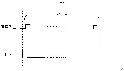
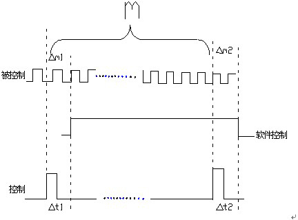
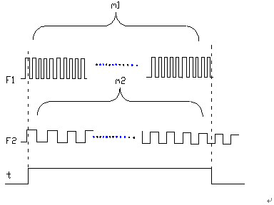
[0073] Pulse modulation is to use a pulse with high output frequency to fill the pulse with low output frequency. This method is the same as the method of measuring frequency or measuring period; the control method of pulse modulation is as follows: Figure II As shown, Ft is t...


PUM


Abstract

The invention discloses an error counter for an electric energy meter. The error counter comprises a single chip, a 10M constant-temperature crystal oscillator, a 5-frequency divider and a 100-frequency divider, wherein four counters are carried by the single chip, and two of the counters are provided with a capturing function. For the error counter provided by the invention, the capturing interrupting and pulse modulation means are adopted, the fuzzy control principle is adopted, and an error counting method with setting parameters subjected to optimized treatment is further adopted, so that the precision for collecting pulses is guaranteed from aspects of hardware design and software design. In addition, the error counter provided by the invention is especially used for solving the problem of controlling the measuring precision and measuring time of low-frequency pulse by the low-frequency pulse. Under the condition of ensuring the measuring precision, the working efficiency is greatly improved.

Description

technical field [0001] The invention relates to a hardware and method of an electric energy meter error calculator applied to a verification device of a 0.01-level three-phase electric energy meter, in particular to an electric energy meter error calculator and an error calculation method. Background technique [0002] The traditional error calculation method is to classify the types of pulses connected to the calibration meter, whether to access high-frequency pulses or low-frequency pulses. This work must be solved before calibration. If in If there is no processing before the calibration, the traditional error calculator may crash or work abnormally; secondly, according to the traditional error calculation method, the user needs to set a lot of parameters to ensure that the error calculator works normally. Both the operator and the user need to distinguish these different parameter types, which increases a lot of trouble in setting; most of the interrupt processing proces...

Claims


Application Information

Patent Timeline
IPC IPC(8): G01R35/04
Inventor 张红陈琳李鹏李哲李琮琮杨静徐鼎
Owner ELECTRIC POWER RESEARCH INSTITUTE OF STATE GRID SHANDONG ELECTRIC POWER COMPANY
Why Eureka
Try Eureka