Intelligent LED (light-emitting diode) video synchronizing impulse stroboscopic supplemental lighting device

A technology of video synchronization and LED lights, which can be used in lighting devices, televisions, optics, etc., and can solve the problems of driver safety hazards, short service life, and high power

Active Publication Date: 2012-08-15
SHANDONG HAIRIFENG ELECTRONICS TECH
View PDF6 Cites 19 Cited by
  • Summary
  • Abstract
  • Description
  • Claims
  • Application Information

AI Technical Summary

Problems solved by technology

[0002] The resolution of high-definition cameras is several times higher than that of traditional analog cameras, and it has relatively high requirements for illumination, especially in automatic license plate number recognition systems, electronic police systems for running red lights, and other public security and traffic monitoring systems. A clear image puts forward higher requirements for the supplementary lighting equipment; the existing system uses electronic flashlights, halogen lamps and other lighting equipment, and the light source for supplementary light is generally a gas flashlight. The working mode of these flashlights is either always on, Either it is just a pulse flash, that is, it never lights up to flashes instantly. The light that flashes in this way is very irritating to people's eyes and nerves. It is a kind of light pollution, which poses a certain safety hazard to the driver. Large size, short service life; and LED lights just overcome the above shortcomings, it is a cold light source, less heat, high efficiency, and life can reach 100,000 hours. Simple, small and light, LED strobe fill light technology has been developed rapidly

Method used


Image

  • Intelligent LED (light-emitting diode) video synchronizing impulse stroboscopic supplemental lighting device
  • Intelligent LED (light-emitting diode) video synchronizing impulse stroboscopic supplemental lighting device
  • Intelligent LED (light-emitting diode) video synchronizing impulse stroboscopic supplemental lighting device

Examples


Embodiment

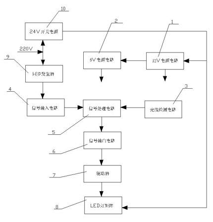
[0042] Embodiment, a kind of intelligent LED video synchronous pulse strobe supplementary light device, refer to Figure 1-Figure 11 , is composed of electronic circuit and shell, the electronic circuit is 220V AC connected to 24V switching power supply 10 and synchronous generator 9, 24V switching power supply 10 connected to LED light matrix 8, +12V power supply circuit 1, +12V power supply circuit 1 connected to +5V power supply Circuit 2, the light detection circuit 3 is connected to the signal processing circuit 5, the signal input circuit 4 is connected to the signal processing circuit 5, the signal processing circuit 5 is connected to the signal output circuit 6, and the signal output circuit 6 is connected to the LED light matrix 8 through the driver 7;

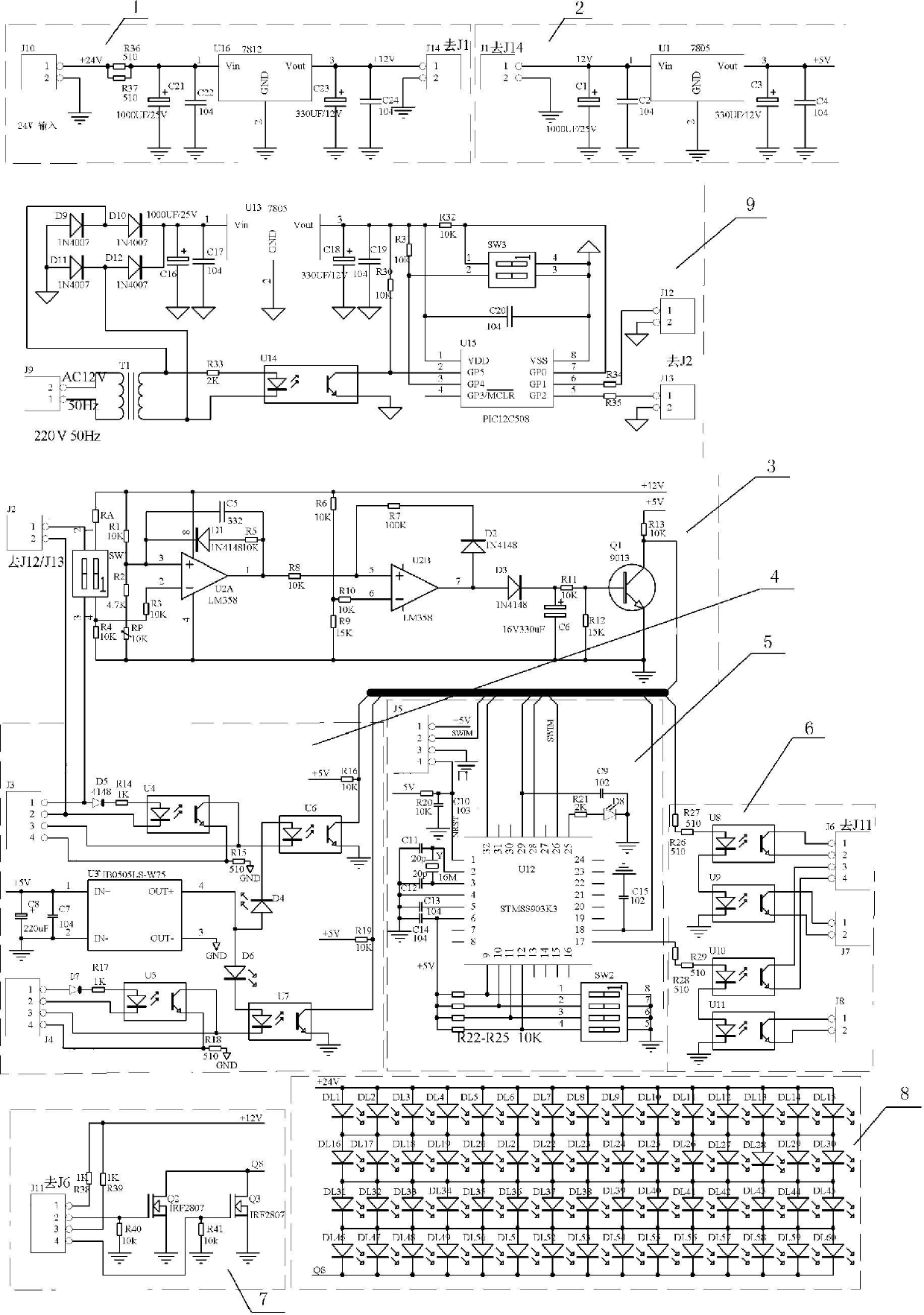
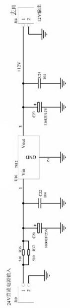
[0043] The 12V power supply circuit 1 is connected with 24V DC power from socket J10, the positive pole of the 24V power supply is connected to pin 1 of socket J10, the negative pole is connected to pin 2 of socket J10...


PUM


Abstract

The invention discloses an intelligent LED (light-emitting diode) video synchronizing impulse stroboscopic supplemental lighting device. The device is composed of an electronic circuit and a shell, wherein the electronic circuit has the following structure: a 220V alternating current is connected with a 24V switching power supply and a synchronization generator, the 24V switching power supply is connected with an LED lamp matrix and a +12V power supply circuit, the +12V power supply circuit is connected with a +5V power supply circuit, a light ray detection circuit is connected with a signal processing circuit, a signal input circuit is connected with the signal processing circuit, the signal processing circuit is connected with a signal output circuit, and the signal output circuit is connected with the LED lamp matrix through an actuator. With the adoption of the device provided by the invention, the phenomena of dazzling, uneven exposure and streaking can be effectively avoided, the synchronous exposure with a frame of a camera and frequency multiplication output of light can be realized, and the problem that the color of the red light in an image shot by a monitoring camera changes from red to yellow during the red light signal of traffic lights is solved.

Description

technical field [0001] The invention belongs to the technical field of outdoor photographic supplementary light equipment, in particular to an intelligent LED video synchronous pulse strobe supplementary light device. Background technique [0002] The resolution of high-definition cameras is several times higher than that of traditional analog cameras, and it has relatively high requirements for illumination, especially in automatic license plate number recognition systems, electronic police systems for running red lights, and other public security and traffic monitoring systems. A clear image puts forward higher requirements for the supplementary lighting equipment; the existing system uses electronic flashlights, halogen lamps and other lighting equipment, and the light source for supplementary light is generally a gas flashlight. The working mode of these flashlights is either always on, Either it is just a pulse flash, that is, it never lights up to flashes instantly. Th...

Claims


Application Information

Patent Timeline
Patent Type & Authority Applications(China)
IPC IPC(8): G03B15/05H05B37/02H04N5/235
CPCY02B20/40
Inventor 宋优文宋伟健宫雪琳梁作信宫立彬
Owner SHANDONG HAIRIFENG ELECTRONICS TECH
Why Eureka
Try Eureka