Segmented iron core

A technology of iron core and iron core column, which is applied in the direction of transformer/inductor magnetic core, inductance/transformer/magnet manufacturing, electrical components, etc. It can solve the problems of transformer coil burnout, easy heating of coil parts, coil burnout, etc., and achieve the best results Good, the method is simple and reliable, and the effect of increasing production costs

Inactive Publication Date: 2012-08-15
无锡希恩电气有限公司
View PDF8 Cites 3 Cited by
  • Summary
  • Abstract
  • Description
  • Claims
  • Application Information

AI Technical Summary

Problems solved by technology

[0002] In the prior art, transformer coils are often burned. After analysis and research, the main reason is that the structure of the air gap is installed between the two ends of the transformer core. The position between the two ends has a large magnetic flux leakage. The coil part is prone to heat, causing local overheating, and the coil will burn out after a long time of use

Method used


Image

  • Segmented iron core
  • Segmented iron core
  • Segmented iron core

Examples


Embodiment Construction

[0014] The present invention will be further described below in conjunction with specific drawings.

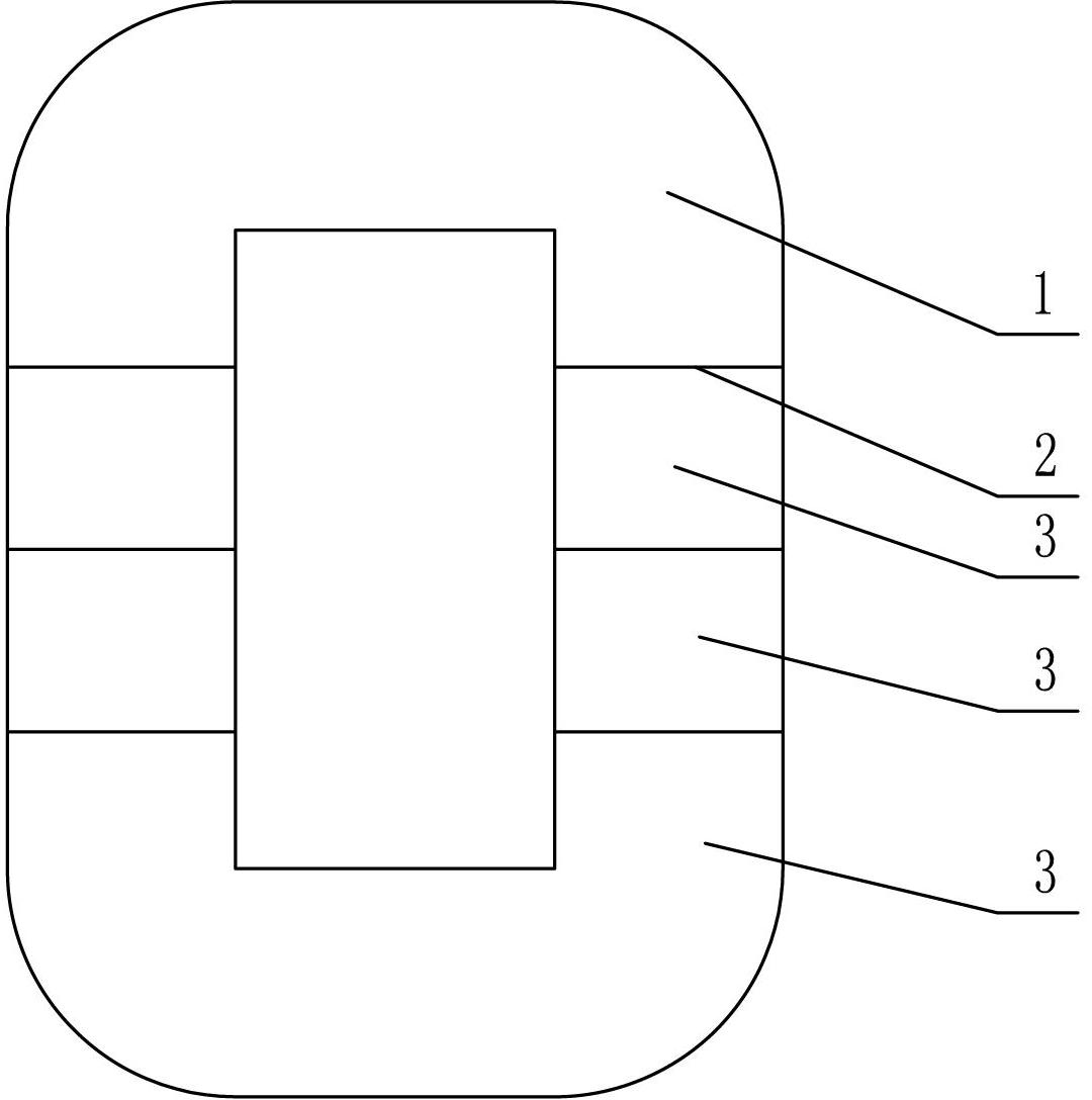
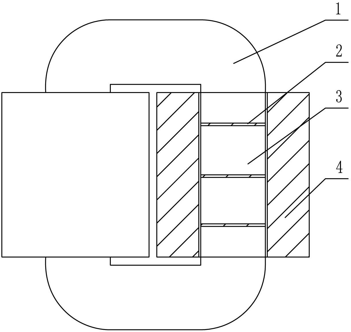
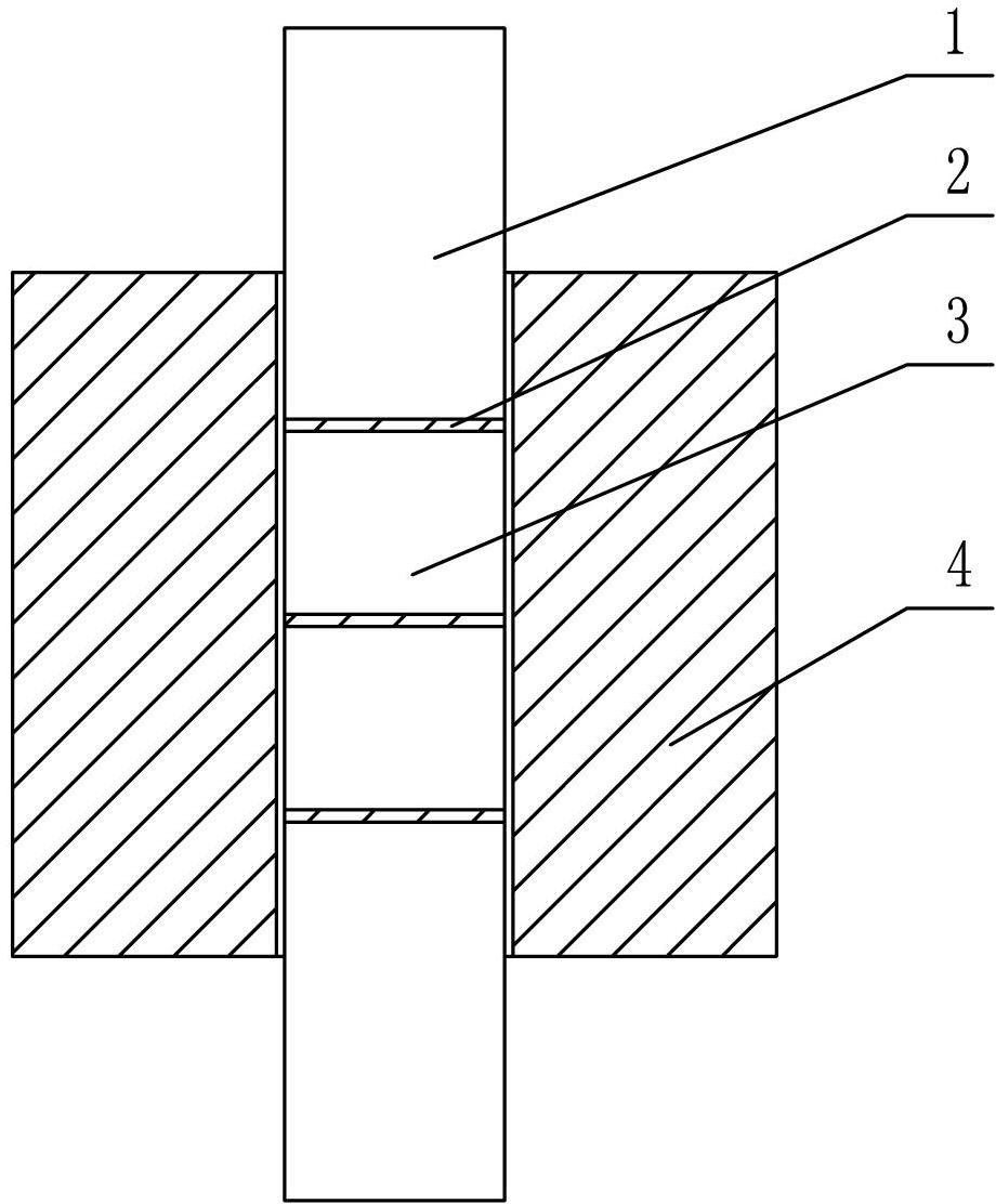
[0015] Such as Figure 1 ~ Figure 3 Shown: Segmented iron core includes iron core body (1), air gap (2), iron core segment (3), coil (4) and so on.

[0016] Such as figure 1 As shown, the present invention includes a rectangular iron core body (1), and three air gaps (2) are respectively arranged on the iron core columns on the left and right sides of the iron core body (1), separating the iron core body (1) into Six sections of iron core section (3);

[0017] The air gap (2) is set on the iron core column where the coil (4) is wound, and the air gap (2) is set on the cutting end surface of the iron core column.

[0018] Such as figure 1 As shown, the present invention divides the iron core body into multi-section iron core segments by increasing the number of cuts on the iron core column, that is, increasing the number of air gaps; figure 2 , image 3 As shown, there a...


PUM


Abstract

The invention relates to a segmented iron core, which comprises an iron core body and is characterized in that the iron core body is provided with multiple air gaps for separating the iron core body into multiple iron core segments; the air gaps are arranged on the iron core body at the part for winding a coil; the iron core body is a rectangular core body; the air gaps are arranged on iron core pillars at the left side and the right side of the rectangular iron core body; each of the iron core pillars at the left side and the right side of the rectangular iron core body is provided with three air gaps; and the iron core body is separated into six iron core segments. By adoption of the segmented iron core, only the cutting times of the iron core pillars need to be increased and other processes do not need to be changed; the method is simple and reliable, the production cost is not increased much, the structure and dimension of a coil do not need to be changed; the segmented iron core is more economic, smaller in volume and better in effect when compared with those obtained by methods of increasing the dimension of a transformer and changing the structure. The number of segments of the iron core pillars can be changed according to requirements and the applicable range is wide.

Description

technical field [0001] The invention relates to an iron core for a transformer coil, especially a segmented iron core. Background technique [0002] In the prior art, transformer coils are often burned. After analysis and research, the main reason is that the structure of the air gap is installed between the two ends of the transformer core. The position between the two ends has a large magnetic flux leakage. The coil part is prone to heat, causing local overheating, and the coil will burn out after a long time of use. Contents of the invention [0003] The purpose of the present invention is to overcome the deficiencies in the prior art, and provide a segmented iron core, so that the magnetic flux leakage on both ends of the iron core can be evenly distributed in multiple positions of the coil, so as to avoid local overheating caused by the concentration of heat in the wire package at the same position conditions that cause burns. [0004] According to the technical sol...

Claims


Application Information

Patent Timeline
Patent Type & Authority Applications(China)
IPC IPC(8): H01F27/24H01F41/02
Inventor 钱明徐惠丰周晓东
Owner 无锡希恩电气有限公司
Why Eureka
Try Eureka