Reactive power compensation device and compensation method

A compensation device and function technology, applied in reactive power compensation, reactive power adjustment/elimination/compensation, etc., to achieve the effects of improving system reliability, compensation accuracy, and compensation reliability

Inactive Publication Date: 2012-08-15
杭州浙泰电气有限公司
View PDF4 Cites 6 Cited by
  • Summary
  • Abstract
  • Description
  • Claims
  • Application Information

AI Technical Summary

Problems solved by technology

Because it adopts the logic circuit principle, it can only realize the point-to-point control mode, and the input and removal can only be done in a cyclic manner, that is, when inputting, it is input in sequence, and when removing, it is a mechanical switching method that is first switched and cut first. The wiring diagram behind the reactive power controller is as follows Figure 7 As shown, the traditional switched capacitor composite switch wiring diagram is shown in Figure 8 shown

Method used


Image

  • Reactive power compensation device and compensation method
  • Reactive power compensation device and compensation method
  • Reactive power compensation device and compensation method

Examples


Embodiment 1

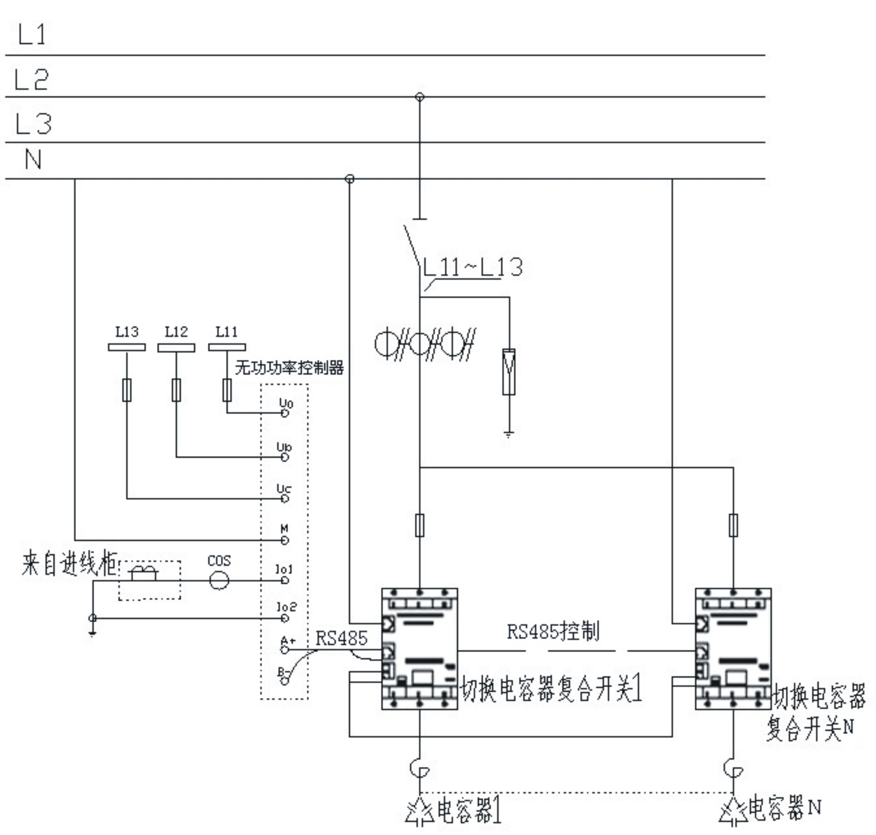
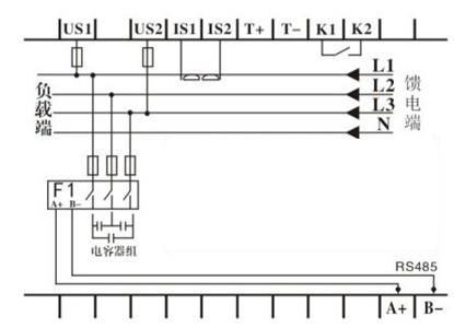
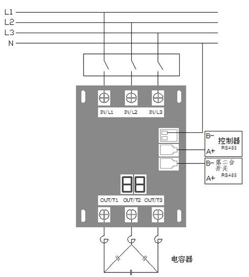
[0016] Embodiment 1: with reference to attached Figure 1-4 . A reactive power compensation device, comprising a reactive power controller, a switching capacitor compound switch, and a power capacitor. The signal output end of the reactive power controller is connected to each signal input end of the switching capacitor compound switch through a networking communication module and an RS486 interface. , to intelligently control the input and removal of power capacitors in each circuit. The signal output terminals of the switching capacitor compound switch are respectively connected with the signal input terminals of the power capacitor. A networking communication module and an RS485 interface are added to the reactive power controller, and a networking communication module and an RS485 interface are added to the supporting switching capacitor composite switch; the communication module and the corresponding communication protocol are connected in series through the RS485 interf...

Embodiment 2

[0017] Embodiment 2: On the basis of Embodiment 1, a compensation method for a reactive power compensation device integrates a professional chip for reactive power compensation and a networked communication module, and reactive power compensation functions such as signal fetching and switching commands are performed by the wireless The power compensation is realized by a professional chip, and the output control system is realized by a networked communication module and an RS485 interface. By installing a networked communication module and a communication protocol on the reactive power controller and switching capacitor composite switch, and adding an RS485 network interface, the The reactive power controller and the RS485 interface of the switching capacitor composite switch are connected in series, and the digital communication address number of each switching capacitor composite switch is edited, so that the entire compensation device forms a local area network to realize var...


PUM


Abstract

The invention relates to a reactive power compensation device and a compensation method, in which an RS485 interface networking communication technology is applied to a control system between a reactive power controller and a combination switch of a switching capacitor. The reactive power compensation device comprises the reactive power controller, the combination switch of the switching capacitor and a power capacitor, wherein a signal output end of the reactive power controller is connected with a signal input end of the combination switch of the switching capacitor respectively through a networking communication module and an RS486 interface, and a signal output end of the combination switch of the switching capacitor is connected with a signal input end of the power capacitor respectively. The reactive power compensation device and the compensation method have the advantages that firstly, the compensation accuracy is improved; secondly, 32-path output is easily realized through one data line of the reactive power controller with the RS485 interface output, for example, by utilizing a specially-made 485 chip, 128 or 256 nodes can be achieved, and 400 nodes can be supported to the maximum degree, therefore, the compensation accuracy of a large-capacity compensation device is solved; thirdly, the compensation reliability is improved; fourthly, the compensation connection is more convenient; fifthly, intelligent compensation is realized; and sixthly, the compensation device has low cost.

Description

technical field [0001] The invention relates to a reactive power compensation device and a compensation method applied to a control system between a reactive power controller and a switching capacitor compound switch by adopting RS485 interface networking communication technology, and belongs to the field of reactive power compensation device manufacturing. Background technique [0002] At present, the traditional control method is that the reactive power controller controls the input or removal of the switching capacitor compound switch through a point-to-point control mode in which one output corresponds to one switching switch, so as to realize the control input or removal of the power capacitor (see principle Image 6 ). Working principle: The traditional reactive power controller analyzes and compares the current sampling information through a special professional chip for reactive power compensation, and then triggers the closing or opening of each relay through the cir...

Claims


Application Information

Patent Timeline
Patent Type & Authority Applications(China)
IPC IPC(8): H02J3/18
CPCY02E40/30
Inventor 张胜雷
Owner 杭州浙泰电气有限公司
Why Eureka
Try Eureka