Elevation-type oil-gas-water three-phase separator with high water ratio

A technology of three-phase separator and high water content, which is applied in the direction of liquid separation, separation method, liquid degassing, etc., to achieve the effect of reducing the probability of outflow, occupying a small area and small volume

Inactive Publication Date: 2012-08-22
SOUTHWEST PETROLEUM UNIV
View PDF5 Cites 8 Cited by
  • Summary
  • Abstract
  • Description
  • Claims
  • Application Information

AI Technical Summary

Problems solved by technology

[0004] The technical problem to be solved by the present invention is to provide a separator with the advantages of both horizontal and vertical separators at the same time, which has the advantages of small size, small footprint, large processing capacity, high efficiency, simple operation and maintenance, and no Lower output hydraulic pressure, almost zero energy consumption elevation-type high water content oil-gas-water three-phase separator

Method used


Image

  • Elevation-type oil-gas-water three-phase separator with high water ratio
  • Elevation-type oil-gas-water three-phase separator with high water ratio
  • Elevation-type oil-gas-water three-phase separator with high water ratio

Examples


Embodiment Construction

[0023] The present invention will be described in detail below in conjunction with the accompanying drawings.

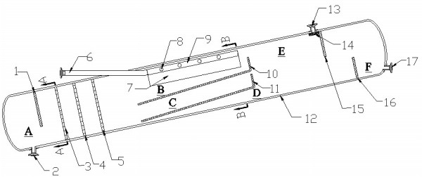
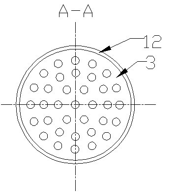
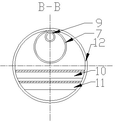
[0024] Such as figure 1 Shown: This device includes weir plate 1, drain port 2, No. 1 orifice plate 3, No. 2 orifice plate 4, No. 3 orifice plate 5, mixture inlet pipe 6, choke tube 7, liquid distribution pipe outlet hole 8. Liquid distribution pipe 9, No. 1 baffle 10, No. 2 baffle 11, tank body 12, exhaust port 13, wire mesh trap 14, air weir plate 15, oil weir plate 16, oil discharge port 17.

[0025] The mixture liquid inlet pipe 6 is placed horizontally, and the right end is connected with the liquid distribution pipe 9 . The liquid distribution pipe 9 and the tank body 12 are placed horizontally, and the discharge holes 8 are evenly and symmetrically spaced on both sides along the pipe direction, and the choke tube 7 is installed on the outside. tangency (eg image 3 As shown), two baffles 10 and 11 parallel to each other are installed under the choke tube 7...


PUM


Abstract

The invention discloses an elevation-type oil-gas-water three-phase separator with a high water ratio, which is characterized in that a tank body is formed at a certain inclination angle with a horizontal direction; a liquid inlet pipe is located at the left-upper part of the tank body and is connected with a liquid distribution pipe which is extended into the tank body and is parallel to the tank body; holes are symmetrically formed on two sides of the liquid distribution pipe evenly along a pipe pass direction; the exterior of the liquid distribution pipe is provided with a choke flow barrel; the outer wall of the top part of the liquid distribution pipe is tangential to the inner wall of the top part of the choke flow barrel; two parallel whirl plates are mounted below the choke flow barrel; the right sides of the whirl plates are a gas dam plate and an oil dam plate; an air exhaust outlet is arranged on the left-upper part of the gas dam plate; a silk net mist catcher is arranged below the air exhaust outlet; a water discharging outlet is arranged on the left-lower side of the tank body; a water dam plate is arranged on the right-upper part of the water discharging outlet; the right side of the water dam plate is provided with three hole plates which are arranged in a parallel manner; and the rightmost side of the tank body is an oil discharging outlet. According to the invention, a structure is simple; an elevation construction has advantages both of a horizontal-type separator and a vertical-type separator simultaneously; the elevation-type oil-gas-water three-phase separator disclosed by the invention is characterized by small volume, little occupancy area, large treatment quantity, high separation efficiency, simple operation and maintenance, non-reduced liquid pressure output, nearly-zero energy consumption and the like.

Description

technical field [0001] The invention relates to a separation and treatment device for a three-phase mixture of oil, gas and water, in particular to an elevation-angle separation device capable of effectively separating a three-phase mixture of oil, gas and water with high water content. Background technique [0002] The oil in the formation is often in gas-liquid two-phase with the change of conditions such as pressure and temperature during the process of extraction. However, in the development of water flooding reservoirs or in the process of water injection production, the products of oil wells often contain a large amount of produced water, and when the oilfield enters a high water cut period, the production of a single well decreases day by day, and the water content of the produced fluid increases rapidly, up to 90%. above. [0003] Traditional three-phase separators are divided into vertical and horizontal. In the gravity settling area and liquid collection area of ...

Claims


Application Information

Patent Timeline
Patent Type & Authority Applications(China)
IPC IPC(8): B01D17/028B01D19/00
Inventor 朱红钧黄坤邹大鹏冯光王其军李新战戚兴张文丽杨晓露
Owner SOUTHWEST PETROLEUM UNIV
Why Eureka
Try Eureka