
Four-point-bending over-bending straightening process method for large shaft tube parts

A four-point bending and process method technology, applied in the mechanical field, can solve the problems of low quality parts, uneven distribution, large residual stress, etc., and achieve the effects of good straightness, reduced straightening times, and increased deformation zone

Inactive Publication Date: 2012-08-22
YANSHAN UNIV
View PDF5 Cites 10 Cited by
  • Summary
  • Abstract
  • Description
  • Claims
  • Application Information

AI Technical Summary

Problems solved by technology

Since the basic mechanical model of its straightening is a three-point bending mechanical model, the main disadvantages of this process are as follows: 1. Because the deformation area is mainly concentrated in the area near the pressure point, the local deformation is serious, resulting in large and distributed residual stress. Uneven, the quality of the parts is not high; 2. The straightening efficiency is low and the labor intensity is high

Method used


Image

  • Four-point-bending over-bending straightening process method for large shaft tube parts
  • Four-point-bending over-bending straightening process method for large shaft tube parts
  • Four-point-bending over-bending straightening process method for large shaft tube parts

Examples


Embodiment 1

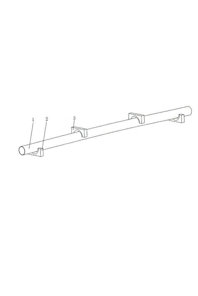
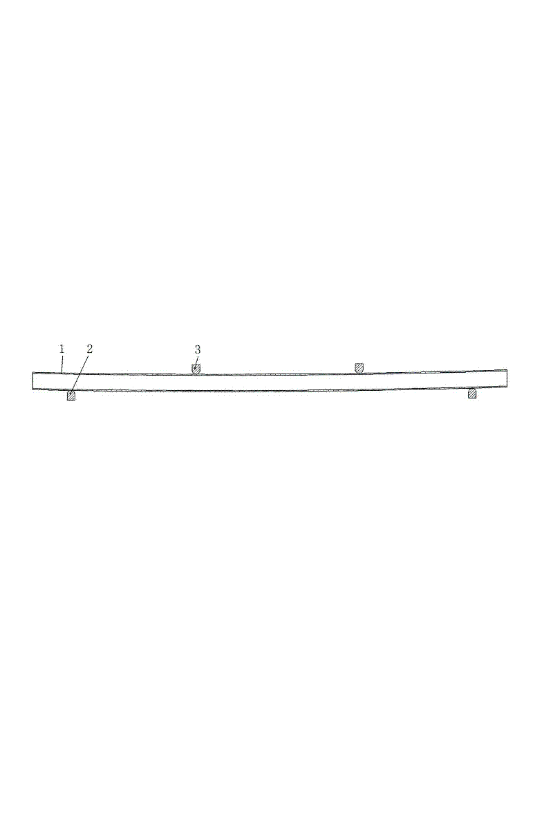
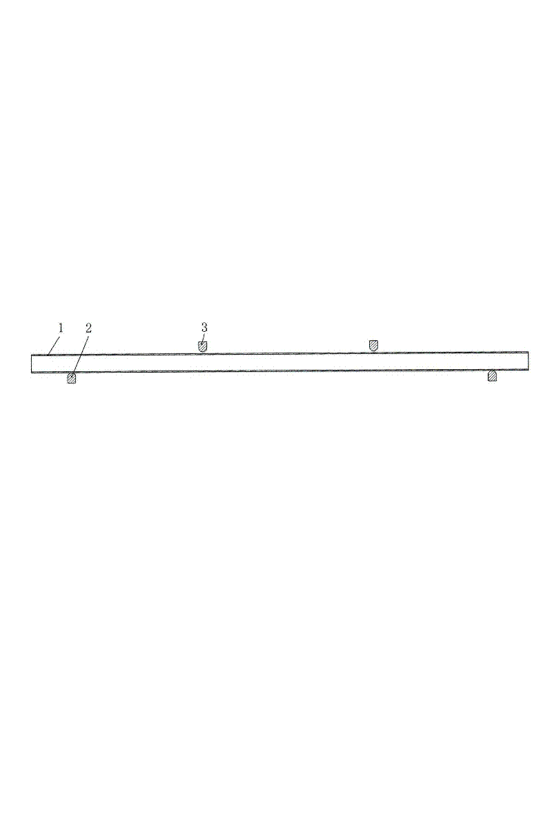
[0024] Example 1: The geometric dimensions of a large longitudinally welded pipe are 457.2 mm in outer diameter, 12.7 mm in wall thickness, 12211 mm in length, and the material is A516Gr60. It can be seen from measurements that its initial deflection is 70 mm. According to the American API Spec 5L industry standard, the straightness of the finished welded pipe, that is, the maximum deflection of the finished pipe, shall not exceed 0.2% of the pipe length, and the length of the pipe is 12211mm, and the final maximum deflection shall not exceed 24mm to meet the straightness requirement. , so it needs to be straightened. It is delivered to the forming press worktable, and placed between two upper molds 3 and two lower molds 2, such as figure 1 shown. The upper ends of the above two upper dies are connected with the beam of the press, and the cross-section of the lower ends is a downwardly convex arc surface. The distance between the two upper dies is adjustable and fixed at 400...

Embodiment 2

[0025] Example 2: Image 6 Shown in is the main schematic diagram of the local working state of Embodiment 2 of the present invention. The upper part of the upper template 13 of the present invention is provided with the same mechanism as the prior art that is connected with the beam of the forming press. The upper edge of the lower surface of the upper template The length and width directions of the upper template are provided with guide grooves, a first vehicle-mounted jack 10 is arranged below, and two independent inserts 4 are arranged on both sides of the first vehicle-mounted jack, by Figure 4 It can be seen that the first vehicle-mounted jack is provided with a vertical guide pin 11, and the upper end of the guide pin is fixed in the width direction guide groove on the upper template. Fix an upper connecting rod 7 with each level of nuts on the two inserts, perforate on both sides of the first vehicle-mounted jack, and pass the screws 9 of the perforations on both side...


PUM

PropertyMeasurementUnit
thicknessaaaaaaaaaa

Abstract

The invention relates to a four-point-bending over-bending straightening process method for large shaft tube parts and is characterized in that two lower dies are arranged on a workbench of a forming press, two upper dies are connected to a beam of the forming press, and a shaft tube part is placed among the two upper dies and the two lower dies under the beam of the forming press; the distance between the two lower dies is determined by calculation, the distance between the two upper dies is determined by calculation, and the positions of the upper dies above the lower dies, and the rolling reduction of the two upper dies are determined by calculation; the distance between the two upper dies and the distance between the two lower dies are respectively adjusted to the expected position; then, the shaft tube part is pressed, after the pressing is finished, the upper dies move upwards along with the beam of the forming press; and whether the straightness of the shaft tube part meets requirements or not is inspected, if not, the steps are repeatedly carried out until the requirements are met. The four-point-bending over-bending straightening process method for the large shaft tube parts has the advantages that the finally-finished shaft tube part is deformed uniformly and realizes smooth transition, and the straightness of the parts better meets the requirements; residual stress existing in the parts is smaller, and the distribution of the residual stress is uniform; and meanwhile, the forming cycle is shortened, and the working efficiency is improved.

Description

technical field [0001] The invention belongs to a mechanical processing method in the field of machinery, and in particular relates to a four-point bending and over-bending straightening process for large-scale shaft and tube parts. Background technique [0002] Shaft tube parts are important parts widely used in mechanical products. Due to heat treatment and other processes, the shaft center line is bent and deformed, which may easily cause the straightness of the parts to fail to meet the use requirements. At present, the straightness quality of the parts can be guaranteed by one or more three-point cold straightening processes. The main forming method is: the shaft tube parts are sent to the forming press table, and placed on an upper die and two lower dies. Between the dies; then, the upper die moves down to press the part into the opposite direction of curvature; then the upper die moves up to measure whether the straightness of the part meets the requirements, if not, ...

Claims


Application Information

Patent Timeline
Patent Type & Authority Applications(China)
IPC IPC(8): B21D3/00
Inventor 赵军展培培马瑞
Owner YANSHAN UNIV
Features
  • Generate Ideas
  • Intellectual Property
  • Life Sciences
  • Materials
  • Tech Scout
  • Unparalleled Data Quality
  • Higher Quality Content
  • 60% Fewer Hallucinations
Learn More