Rotary type compressor
A technology of rotary compressor and compression mechanism, applied in the direction of pump combination, mechanical equipment, machine/engine, etc. for elastic fluid rotary piston type/oscillating piston type, can solve the alignment error of spindle and motor bearing, motor bearing And the main bearing wear and other problems, to reduce the amount of deformation, solve the effect of increased vibration and operational reliability
- Summary
- Abstract
- Description
- Claims
- Application Information
AI Technical Summary
Problems solved by technology
Method used
Image
Examples
Embodiment 1
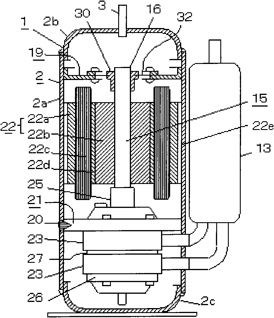
[0028] see figure 1 , The pressure in the sealed casing 2 of the rotary compressor 1 is the high-pressure side pressure, and the sealed casing 2 is composed of a cylindrical middle casing 2a, an upper casing 2b, and a lower casing 2c. A motor 22 and a double-cylinder rotary compression mechanism 21 driven by the motor 22 are accommodated in the sealed casing 2 . The motor 22 includes a stator 22a and a rotor 22b.
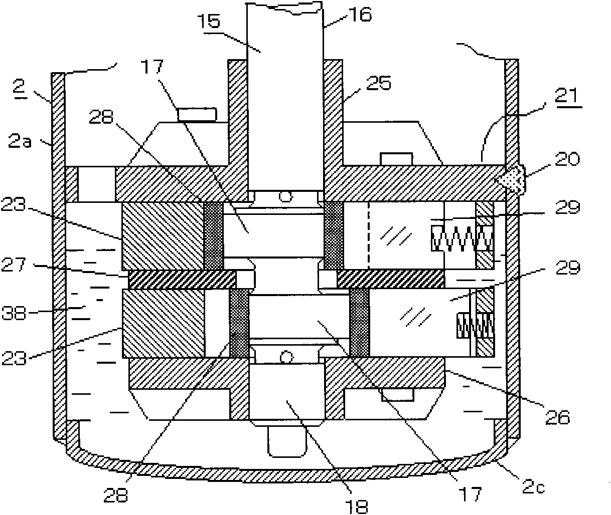
[0029] see figure 2 , the compression mechanism 21 is divided into two cylinders 23 by a middle partition 27, a piston 28 and a sliding plate 29 respectively accommodated in each cylinder 23, an eccentric crankshaft 15 for eccentrically driving the piston 28, a main bearing 25 and an auxiliary bearing 26, etc. . The middle part of the cylinder 23 is provided with a cylinder compression chamber, and the piston 28 rotates eccentrically in the cylinder compression chamber. The sliding plate 29 reciprocates under the eccentric rotation of the piston 28 .
[0030] ...
Embodiment 2
[0068] see Figure 10 In Embodiment 2, after the bearing bracket 31 is fixed on the inner wall of the intermediate housing 2a, the elastic plate 32 connected with the central bearing 30 is fixed on the bearing bracket. Therefore, the elastic plate 32 can be fixed or removed from the bearing bracket 31 through the bearing screws 39 .
[0069] There is a gap between the mounting hole of the elastic plate 32 and the bearing screw 39 , so that it can move in the horizontal direction relative to the bearing bracket 31 . Thus, the main shaft 16 and center bearing 30 can be properly aligned. After centering, the elastic plate 32 is fixed on the bearing bracket 31 with bearing screws 39 .
[0070] As a result, compared with Embodiment 1, the alignment of the main shaft 16 and the center bearing 30 can be more in place. Moreover, the elastic plate 32 is fixed on the bearing bracket 31 in advance, and after the main shaft 16 and the center bearing 30 are aligned, the center bearing 3...
Embodiment 3
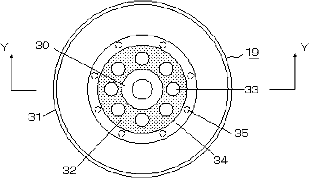
[0073] Embodiment 3 can further reduce the amount of oil ejection related to the adjustment hole 33 provided in the elastic plate 32 disclosed in Embodiment 1.
[0074] see Figure 11 , an oil separation plate 40 may be provided between the rotor 22 b and the elastic plate 32 . As a result, the gap between the elastic plate 32 and the oil separation plate 40 is reduced. The oil separation plate 40 is made up of a circular plate about the same size as the elastic plate 32 and a cylinder mounted on the outer wall of the main shaft 16 .
[0075] The high-pressure gas discharged from the compression mechanism 21 reaches the exhaust pipe 3 after passing through the adjustment hole 33 through the gap between the oil separation plate 40 and the elastic plate 32 .
[0076] The oil particles contained in the high-pressure gas fly outward along the tangential direction of the oil separation plate 40 through the oil separation plate 40 rotating together with the main shaft 16 .
[007...
PUM
 Abstract
Description
Claims
Application Information
 - R&D
- Intellectual Property
- Life Sciences
- Materials
- Tech Scout
- Unparalleled Data Quality
- Higher Quality Content
- 60% Fewer Hallucinations
Browse by: Latest US Patents, China's latest patents, Technical Efficacy Thesaurus, Application Domain, Technology Topic, Popular Technical Reports.
© 2025 PatSnap. All rights reserved.Legal|Privacy policy|Modern Slavery Act Transparency Statement|Sitemap|About US| Contact US: help@patsnap.com


