
Micro thermal drive airflow gyro and manufacture method thereof

A production method and heat-driven technology, applied in the direction of steering sensing equipment, etc., can solve the problems of poor sensor sensitivity, low heat flow rate, and difficult production, and achieve the effects of suppressing thermal convection, increasing thermal expansion/contraction flow, and reducing sensitivity effect of influence

Active Publication Date: 2012-08-22
TSINGHUA UNIV
View PDF9 Cites 46 Cited by
  • Summary
  • Abstract
  • Description
  • Claims
  • Application Information

AI Technical Summary

Problems solved by technology

The first two structures contain driving moving parts, which are complicated in structure and difficult to manufacture; the third structure is simple and easy to manufacture, but the heat flow velocity is low, the sensor sensitivity is poor, and the heat convection velocity used is also affected by longitudinal acceleration. Gyro sensitivity is related to external acceleration

Method used


Image

  • Micro thermal drive airflow gyro and manufacture method thereof
  • Micro thermal drive airflow gyro and manufacture method thereof
  • Micro thermal drive airflow gyro and manufacture method thereof

Examples


Embodiment Construction

[0027] The specific implementation manners of the present invention will be further described in detail below in conjunction with the accompanying drawings and embodiments. The following examples are used to illustrate the present invention, but are not intended to limit the scope of the present invention.

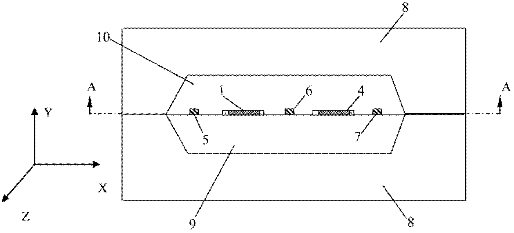
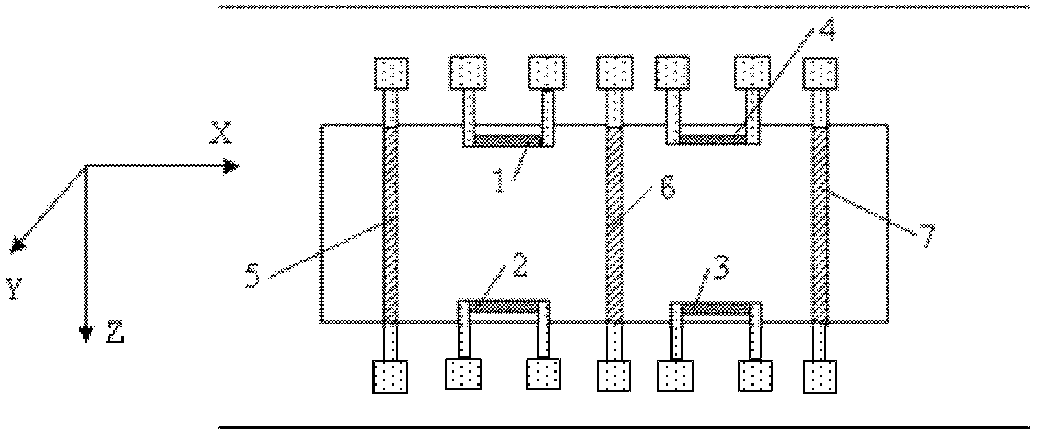
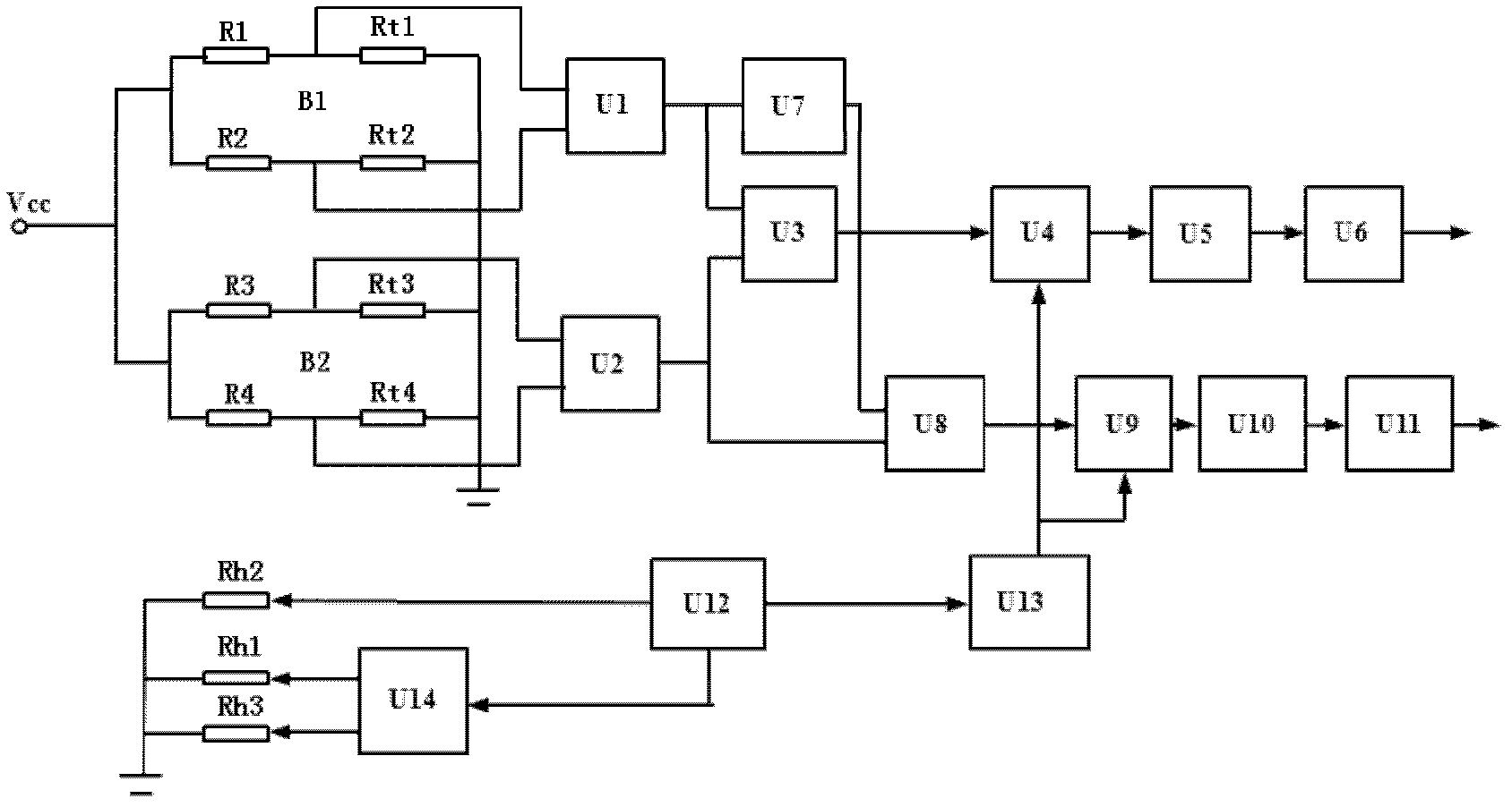
[0028] The structure of a kind of miniature heat-driven airflow gyroscope of the present embodiment is as follows: figure 1 as shown, figure 2 yes figure 1 Referring to the top sectional view of A-A direction in the figure, the gyroscope of this embodiment includes: a microcavity, three heating elements, two pairs of heat-sensitive elements, a detection circuit and a control circuit module. Specifically, the microcavity is made up of a lower cavity 9 and an upper cavity 10, both of which are etched on a silicon wafer 8 by bulk silicon etching technology, and will have an upper cavity 10 or The two silicon wafers 8 of the lower cavity 9 structure are pasted together by ...


PUM


Abstract

The invention relates to a micro angle speed sensor, in particular to a micro thermal drive airflow gyro, which comprises a micro cavity body, three heating elements, two pairs of thermosensitive elements, a detection circuit and a control circuit module. The height of the micro cavity body is 100mu-1000mu, the heating elements and the thermosensitive elements are fixed in the micro cavity body in a suspended mode, the heating elements are parallelly arranged in the micro cavity body in a left-and-right mode, a pair of thermosensitive elements is arranged between two adjacent heating elements, and each pair of thermosensitive elements is symmetrically distributed on the front side and the rear side of the micro cavity body. The detection circuit can detect temperature signals of the thermosensitive elements, and the control circuit can control heating of the heating elements. By means of the micro thermal drive airflow gyro, a thermal expansion flow or a contraction flow of air in the micro cavity body is stable, controllability of the air flow is good, thermal convection is effectively inhibited, and influences of outside acceleration on sensitivity of the sensor are reduced.

Description

technical field [0001] The invention relates to a miniature angular velocity sensor, in particular to a miniature heat-driven airflow gyroscope and a manufacturing method thereof. Background technique [0002] Miniature, high-performance inertial sensors have a wide range of application requirements in aviation, aerospace, vehicles, ships, robots and other industries, and micro-angular rate gyroscopes are one of them. Conventional micro-angular rate gyroscopes use a solid mass to vibrate, and use capacitance to detect the movement of the mass produced by Coriolis force in the direction perpendicular to the driving direction. The advanced silicon processing technology is relatively difficult, which leads to poor reliability and low product qualification rate. [0003] The fluid-based angular velocity sensor replaces the moving mass with fluid, which can not only simplify the sensing structure, but also greatly improve the impact resistance of the sensor. Angular velocity se...

Claims


Application Information

Patent Timeline
Patent Type & Authority Applications(China)
IPC IPC(8): G01C19/58
Inventor 朱荣蔡嵩林丁衡高
Owner TSINGHUA UNIV
Learn More