
System and method using electronic deflection to form flying spot

An electronic deflection and flying spot technology, applied in the field of X-ray imaging, can solve the problems of limited flying spot moving speed, slow moving speed of flying spot, etc., and achieve the effect of improving efficiency

Inactive Publication Date: 2012-08-22
SHANGHAI EASTIMAGE EQUIP
View PDF3 Cites 6 Cited by
  • Summary
  • Abstract
  • Description
  • Claims
  • Application Information

AI Technical Summary

Problems solved by technology

[0007] The purpose of the embodiment of the present invention is to solve the problem that the moving speed of the flying point is limited by the mechanical movement in the prior art, which leads to the problem that the moving speed of the flying point is too slow, and propose a system and method for forming a flying point by using electronic deflection

Method used


Image

  • System and method using electronic deflection to form flying spot
  • System and method using electronic deflection to form flying spot
  • System and method using electronic deflection to form flying spot

Examples


Embodiment Construction

[0032] The present invention will be described in further detail below in conjunction with the accompanying drawings.

[0033] like Figure 4 As shown, it is a schematic composition diagram of a system using electronic deflection to form flying spots according to an embodiment of the present invention. The system includes:

[0034] X-ray source, the X-ray source has a deflection coil, the magnetic field of the deflection coil deflects the electrons emitted by the cathode to form deflected electrons, and the deflected electrons fall on the anode target to form an X-ray beam;

[0035] A pinhole device, the pinhole device is located at the beam output window of the ray source, and transmits the X-ray beam to form flying spots.

[0036] In the embodiment of the present invention, the target point of the X-ray source can be changed, and the change of the target point is realized by deflecting the target electrons by the magnetic field, and then cooperates with the pinhole device t...


PUM


Abstract

The invention discloses a system using an electronic deflection to form flying spot radiation and a flying spot scanning method. The system comprises an X-ray source and a pinhole device, wherein the X-ray source has a deflecting coil, an electron emitted by a cathode is deflected by a magnetic field of the deflecting coil to form a deflection electron, the deflection electron falls on an anode target spot to form an X-ray beam, and a transmission is performed by the pinhole device to the X-ray beam to form a flying spot. By mean of the embodiment of the system and the method using the electronic deflection to form the flying spot, the movement speed of the flying spot is not limited by the mechanical motion, the light velocity can be theoretically reached, and the scanning efficiency using the flying spot is improved.

Description

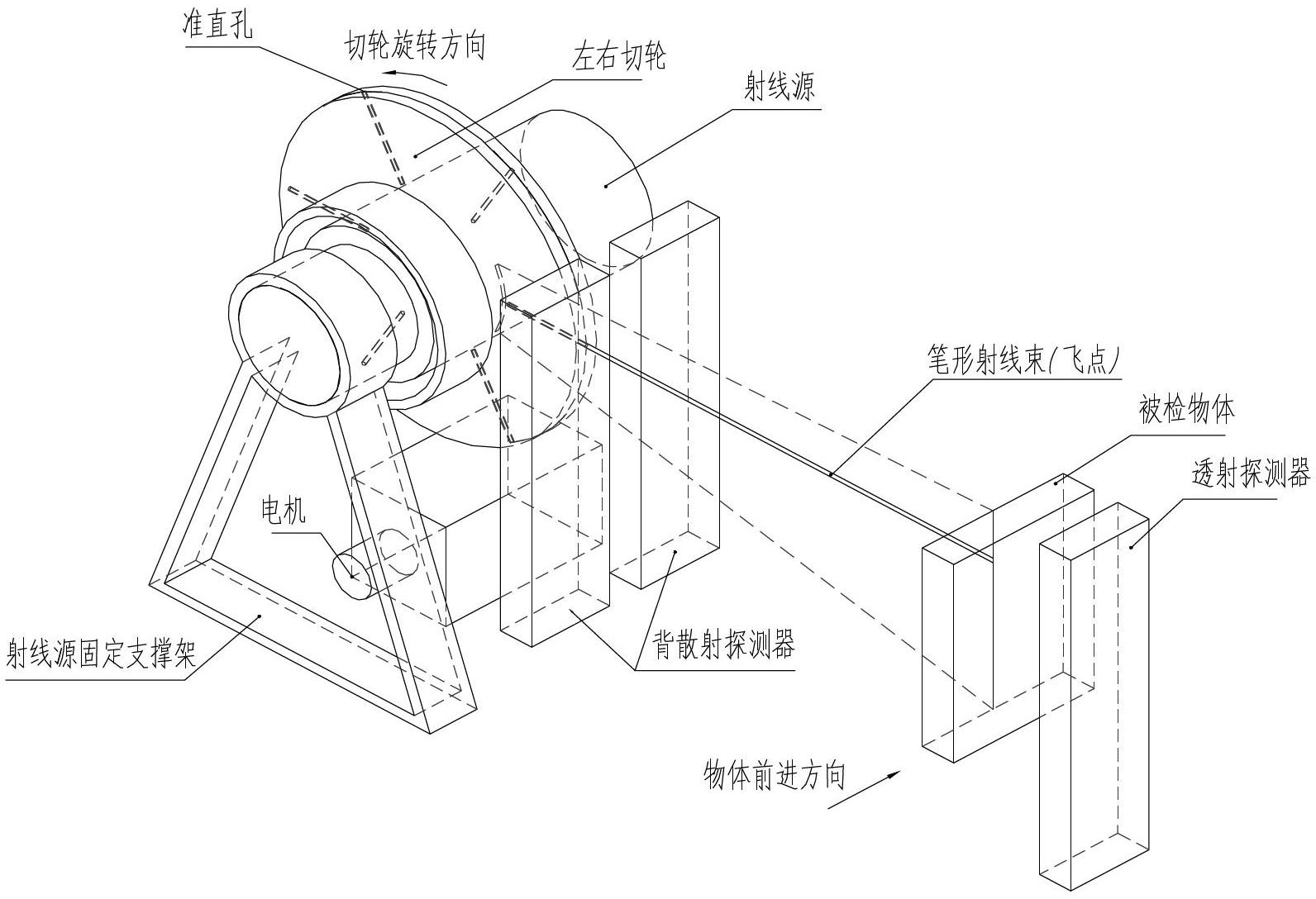
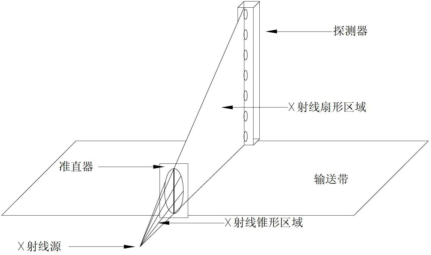
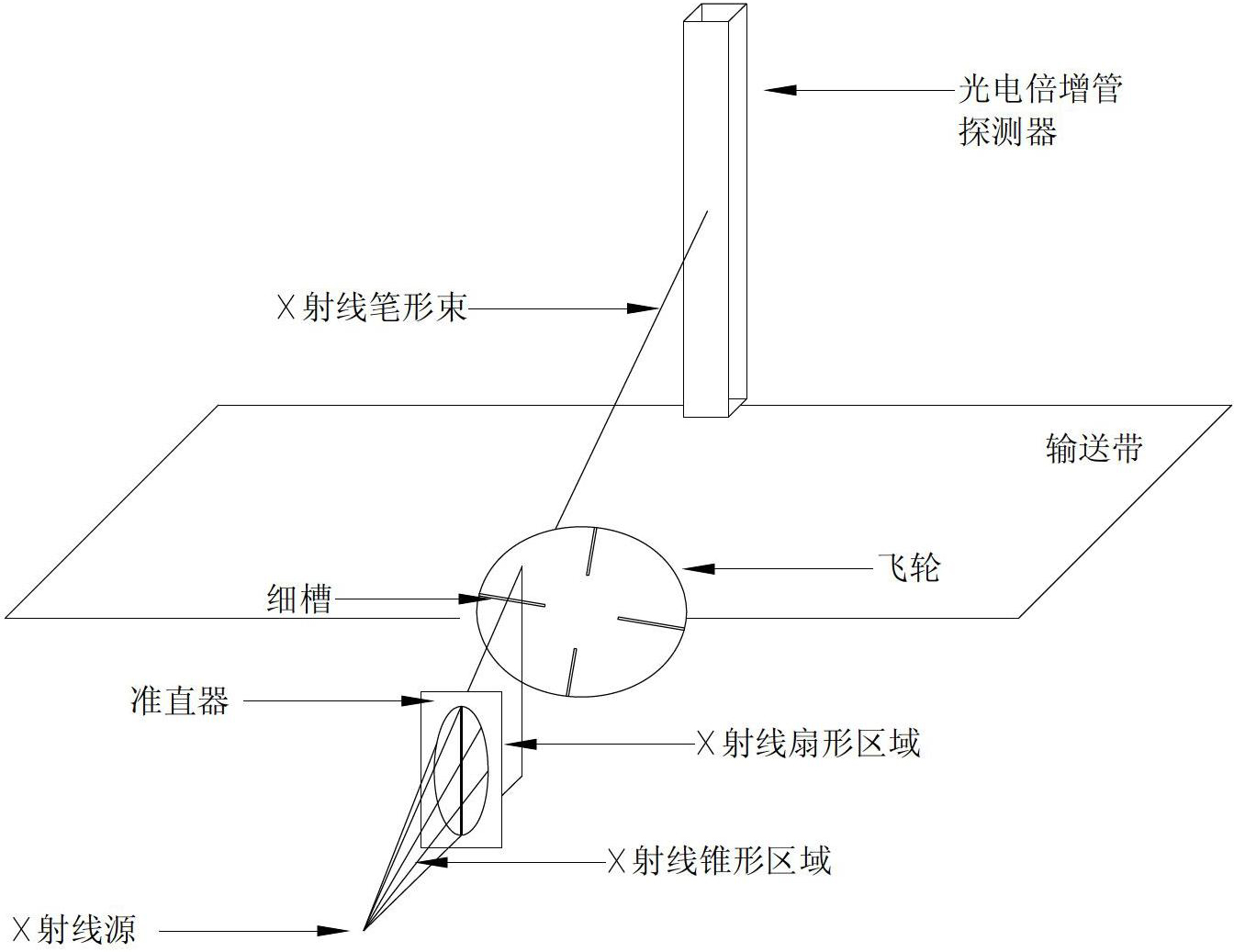
technical field [0001] The invention relates to the technical field of X-ray imaging, in particular to a system and method for forming flying spots by electronic deflection. Background technique [0002] Currently, there are two main methods of flying-spot scanning for X-ray imaging: [0003] a kind of like figure 1 As shown: the rotating wheel (called the left and right cutting wheels in the figure) is evenly arranged with small conical holes along the radial direction, so that the rays emitted at the center of the circle can be shot out along the small conical holes and fall on the object to form circular spots. Namely fly point. This method is described in detail in the patent (patent number: ZL03801115.8, invention name: mobile X-ray backscatter inspection vehicle, inventor: American Science and Technology Engineering Corporation), in this typical flying point system, X A thin "pencil beam" of rays rapidly and repeatedly sweeps through a vertically oriented "fan" cent...

Claims


Application Information

Patent Timeline
IPC IPC(8): G01N23/04
Inventor 屈俊健梁石磊王国岭
Owner SHANGHAI EASTIMAGE EQUIP
Learn More