
High-dielectric-material super capacitor with porous structure

A high-dielectric material and porous structure technology, applied in capacitor electrodes, capacitor parts, capacitor dielectric layers, etc., can solve the problems of poor safety, small leakage current, low power density, etc. Energy storage density, the effect of increasing the capacitance

Inactive Publication Date: 2012-08-22
符建
View PDF6 Cites 4 Cited by
  • Summary
  • Abstract
  • Description
  • Claims
  • Application Information

AI Technical Summary

Problems solved by technology

[0003] These two technologies have their own advantages and disadvantages in power storage applications: Lithium-ion batteries have the advantages of high energy storage density and low leakage current, but they have the advantages of less cycle times, short life, long charging time, low power density, and poor safety. Disadvantages: supercapacitors have the advantages of short charging time, high power density, high cycle times and long life, but at present, the energy storage density of supercapacitors is only about one tenth of that of batteries, and it is difficult to replace batteries to realize large-scale power storage applications
However, these two methods require a lot of stacked structures to achieve large capacitance, which is very difficult to prepare, and on the other hand, the surface area that this planar structure can provide is very limited.

Method used


Image

  • High-dielectric-material super capacitor with porous structure
  • High-dielectric-material super capacitor with porous structure
  • High-dielectric-material super capacitor with porous structure

Examples


Embodiment Construction

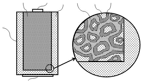
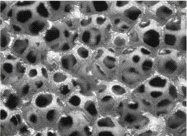
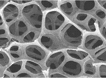
[0029] Such as figure 1 As shown, the high dielectric material porous structure supercapacitor includes a porous metal high dielectric material composite substrate 1, a low melting point metal medium 2, a sealed container 3, a positive electrode 4, and a negative electrode 5; the porous metal high dielectric material composite substrate 1 is A porous material formed by depositing one or more layers of high dielectric material 7 on the surface of the metal foam skeleton 6, the porous metal high dielectric material composite substrate 1 is soaked in the low melting point metal medium 2, and is packaged in a sealed container 3, The porous metal high dielectric material composite substrate 1 is connected to the positive electrode 4, and the conductive liquid medium 2 is connected to the negative electrode 5 to form a supercapacitor for accumulating electric energy.

[0030] The high dielectric material 7 is BaTiO 3 or CaCu 3 Ti 4 o 12 High dielectric constant material, or two ...


PUM

PropertyMeasurementUnit
porosityaaaaaaaaaa

Abstract

The invention discloses a high-dielectric-material super capacitor with a porous structure. The high-dielectric-material super capacitor comprises a porous-metal high-dielectric-material composite substrate, a low-melting-point metal medium, a sealed container, a positive electrode and a negative electrode, wherein the porous-metal high-dielectric-material composite substrate is a porous material formed by depositing one layer or multilayer of high dielectric materials on the surface of a foam metal framework; the porous-metal high-dielectric-material composite substrate is soaked in the low-melting-point metal medium and is packaged in the sealed container; and the porous-metal high-dielectric-material composite substrate is connected with the positive electrode; a conductive liquid medium is connected with the negative electrode so as to form the super capacitor for accumulating electric energy. According to the high dielectric material super capacitor provided by the invention, a capacitor with high capacity can be realized by utilizing the very large surface area of the porous electrode and the high dielectric coefficient of BaTiO3 or CaCu3Ti4O12, so that the problem of low working voltage of the existing super capacitor is solved. Therefore, the capacitor can obtain an extremely high energy accumulation density.

Description

technical field [0001] The invention relates to a supercapacitor for storing electric energy, in particular to a supercapacitor with a porous structure of high dielectric material. Background technique [0002] At present, there are two main storage technologies, one is lithium-ion battery: using lithium (Li + ) The chemical reaction of ions between the anode and the cathode realizes the charging and discharging process, and the other is the supercapacitor: a double-layer capacitor structure with a huge capacity is formed by using the huge surface area of ​​the porous electrode and the extremely small spacing, and the charging and discharging is realized through a physical process. [0003] These two technologies have their own advantages and disadvantages in power storage applications: Lithium-ion batteries have the advantages of high energy storage density and low leakage current, but they have the advantages of less cycle times, short life, long charging time, low powe...

Claims


Application Information

Patent Timeline
Patent Type & Authority Applications(China)
IPC IPC(8): H01G9/04H01G9/07
CPCY02E60/13
Inventor 符建
Owner 符建
Learn More