Micro generator

A micro-generator, pin base technology, applied in electrical components and other directions, can solve the problems of high environmental requirements, low service life, unpleasant power generation, etc., to achieve the effect of reasonable and simple structure design, reasonable structure design, convenient and reliable use

Inactive Publication Date: 2012-08-22
湖州九州信义科技有限公司
View PDF3 Cites 0 Cited by
  • Summary
  • Abstract
  • Description
  • Claims
  • Application Information

AI Technical Summary

Problems solved by technology

[0002] The volume, weight and power of the batteries currently on the market can meet the market demand, but the ambient temperature and service life during use are difficult to meet the requirements of an ambient temperature between -30°C and +60°C and a service life of 10 years.
This is because chemical batteries mainly have the following three deficiencies: first, the storage time is short, even in an environment that meets storage and transportation conditions, the validity period of American military batteries is only 5 years; High environmental requirements, such as high temperature, low temperature, waterproof, moisture-proof, etc.; third, poor adaptability to low temperature and high temperature, for example, the discharge capacity drops significantly at low temperature, and it is easy to leak and corrode at high temperature, etc.
[0004] In addition, there are other patent applications for inventions and utility models of micro-generators, but their structural design is even more unreasonable and cannot be applied to linear generators, only to turbo-generators
At the same time, the generator structures disclosed in the prior art cannot be simply combined, even with the addition of common knowledge, otherwise the use effect will be even worse: either resulting in high cost, or resulting in large volume and heavy weight, or resulting in low service life , or lead to unsatisfactory power generation, or to impossibility of implementation, or to a combination of the above disadvantages

Method used


Image

  • Micro generator
  • Micro generator
  • Micro generator

Examples


Embodiment Construction

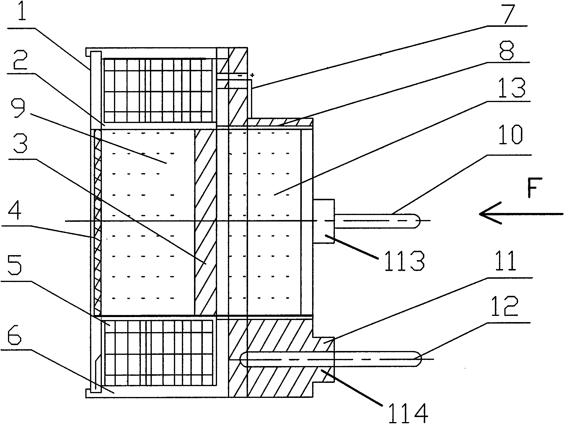
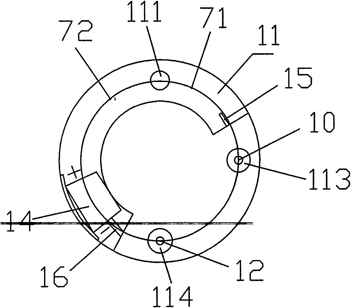
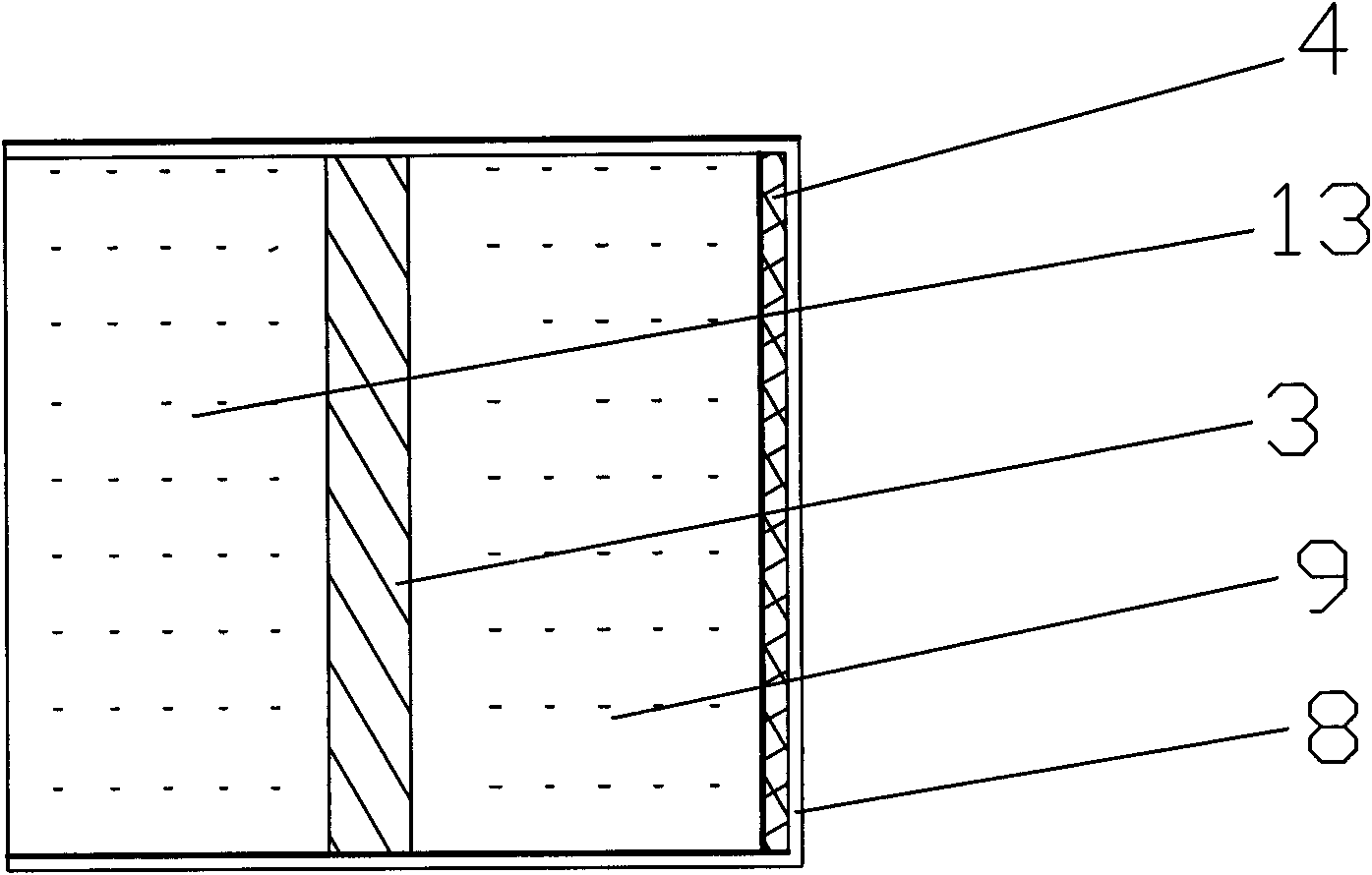
[0026] see Figure 1 to Figure 5 The structure of the embodiment of the present invention includes a housing, a coil, a bobbin 2, a magnet one 9, an iron core 3, a magnet two 13, a pole piece 4, a magnet sleeve 8, a pin base 11, an output negative pole 10 and The positive pole 12 at the output end; the casing includes a shell 6 and an end piece 1 , and the coil is formed by winding an enameled wire 5 in a coil skeleton 2 .

[0027] In this embodiment, the end piece 1 is matched with the shell 6, the pin base 11 is attached to the shell 6, one end of the magnetic steel sleeve 8 is open and the middle part is a cavity structure, and the magnetic steel sleeve 8 is located in the middle of the entire generator ; Pole shoe 4, magnet one 9, iron core 3 and magnet two 13 are installed in the magnet sleeve 8 in sequence, and the polarity of magnet one 9 is opposite to that of magnet two 13; magnet one 9 and magnet two 13 In the magnetic steel sleeve 8, the iron core 3 and the pole sh...


PUM


Abstract

The invention relates to a micro generator, which comprises a shell body, a coil, an output-end anode and an output-end cathode, wherein the coil is installed in the shell body; the shell body comprises an outer shell and an end sheet and is provided with magnetic steel 1, an iron core, magnetic steel 2, a pole shoe, an magnetic steel sleeve and a pin base. The end sheet is matched with the outer shell, and the pin base is fitted with the outer shell. One end of the magnetic steel sleeve is open, and the middle part of the magnetic steel sleeve is a hollow cavity. The pole shoe, the magnetic steel 1, the iron core and the magnetic steel 2 are sequentially installed in the magnetic steel sleeve to form a magnetic steel assembly, and the polarities of the magnetic steel 1 and the magnetic steel 2 are opposite. The coil and the pin base form a coil assembly, and the magnetic steel assembly is arranged in the coil assembly. The output-end anode and the output-end cathode are fixed on the pin base, and coil outgoing lines are respectively connected with the output-end anode and the output-end cathode through a small hole of the outer shell and a small hole of the pin base. The micro generator has the advantages of reasonable and simple structure design, small volume, light weight, low cost, convenience and reliability in use, good effect and long service life and can save a good magnetic permeability function for a long term, and power generation is fast.

Description

technical field [0001] The invention relates to a micro-generator, in particular to a micro-generator which can be stored for a long time and adapted to various complicated environments, which belongs to a kind of linear generator. Background technique [0002] The size, weight and power of the batteries currently on the market can meet the market demand, but the ambient temperature and service life during use are difficult to meet the requirements of an ambient temperature between -30°C and +60°C and a service life of 10 years. This is because chemical batteries mainly have the following three deficiencies: first, the storage time is short, even in an environment that meets storage and transportation conditions, the validity period of American military batteries is only 5 years; High environmental requirements, such as high temperature, low temperature, waterproof, moisture-proof, etc.; third, poor adaptability to low temperature and high temperature, for example, the disch...

Claims


Application Information

Patent Timeline
Patent Type & Authority Applications(China)
IPC IPC(8): H02K57/00
Inventor 陈立新
Owner 湖州九州信义科技有限公司
Why Eureka
Try Eureka