2D hydraulic-power-assisted electro-hydraulic proportional reversing valve

A proportional reversing valve and power-assisted electric technology, which is applied in the direction of fluid pressure actuators, servo motor components, mechanical equipment, etc., can solve the problem of leakage flow of pilot and control stages that cannot work normally, large flow of pilot-control electro-hydraulic proportional valves, Problems such as stagnant guide and control stage oil circuit, etc., to overcome adverse effects, high working pressure, and improve accuracy

Active Publication Date: 2012-08-29
ZHEJIANG UNIV OF TECH
View PDF5 Cites 56 Cited by
  • Summary
  • Abstract
  • Description
  • Claims
  • Application Information

AI Technical Summary

Problems solved by technology

[0008] In order to overcome the existing electro-hydraulic proportional valve's susceptibility to friction, hydraulic power and oil pollution, the phenomenon of "stuck" and the loss of pressure in the oil circuit of the pilot and control stage or the pressure is too low make the entire valve unable to work normally and the pilot and control stage Due to the large leakage flow rate, the present invention provides an ordinary pilot-controlled electro-hydraulic proportional valve that not only has the characteristics of large flow rate and high working pressure, but also can be realized like a direct-acting proportional valve under zero pressure (pressure loss). 2D hydraulic power-assisted electro-hydraulic proportional reversing valve with proportional control function

Method used


Image

  • 2D hydraulic-power-assisted electro-hydraulic proportional reversing valve
  • 2D hydraulic-power-assisted electro-hydraulic proportional reversing valve
  • 2D hydraulic-power-assisted electro-hydraulic proportional reversing valve

Examples


Embodiment Construction

[0020] The present invention will be further described below in conjunction with the accompanying drawings.

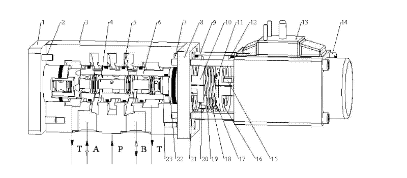
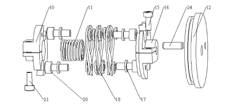
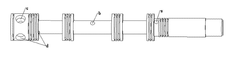
[0021] refer to Figure 1 ~ Figure 4d , a 2D hydraulic power-assisted electro-hydraulic proportional reversing valve, including a linear electro-mechanical converter (such as a proportional electromagnet, or other linear electro-mechanical converter) 13, a section 10 of a compression-torsion coupling, a sleeve 9, Centering spring 19, reed 18, washer 17, support spring 11, pressure torsion coupling section b 16, fixed plate 12, cylindrical pin 24, left cover 1, valve body 3, valve sleeve 6, valve core 4 , Right cover plate 8, right plug ring 22, concentric ring 23, O-ring 5 and screws 2, 7, 14, 15, 20, 21.

[0022] The linear electro-mechanical converter (such as a proportional electromagnet, or other linear electro-mechanical converter) 13 is used as an electro-mechanical converter to drive a 2D hydraulic power-assisted electro-hydraulic proportional reversing (thrott...


PUM


Abstract

The invention provides a 2D (2-dimensional) hydraulic-power-assisted electro-hydraulic proportional reversing valve, which comprises a valve body, a valve core, a valve sleeve, a linear electro-mechanical converter and a compressive-torsional coupling, wherein the valve core, the compressive-torsional coupling and the linear electro-mechanical converter are coaxially connected; an output shaft of the linear electro-mechanical converter is fixedly connected with an input end of the compressive-torsional coupling; an output end of the compressive-torsional coupling is fixedly connected with the right end of the valve core; a sensitive cavity is formed by the left end of the valve core, the valve sleeve and a left cover plate; a pair of axisymmetric high pressure holes and a pair of axisymmetric low pressure holes are respectively formed on the surfaces of shoulders of the valve core in the sensitive cavity; a pair of axisymmetric sensing channels are arranged on the inner surface of the valve sleeve outside the sensitive cavity; and one end of each receptive channel is communicated with the sensitive cavity, and the other ends of the receptive channels cover areas between adjacent high pressure holes and low pressure holes. The 2D hydraulic-power-assisted electro-hydraulic proportional reversing valve not only has the characteristics of high flow rate, high working pressure, and the like of an ordinary pilot-control type electro-hydraulic proportional valve, but also fulfils a proportional control function like a direct-actuated proportional valve under the circumstance of zero pressure (pressure loss).

Description

technical field [0001] The invention belongs to an electro-hydraulic proportional valve in the field of fluid transmission and control, in particular to an electro-hydraulic proportional reversing valve. Background technique [0002] Since the advent of the electro-hydraulic servo system in the 1940s and 1950s, it has been widely used in aviation, Aerospace, automatic weapons, steel, power stations and other important national strategic industrial fields have been applied and achieved rapid success. Naturally, people also hope that the ordinary hydraulic transmission system can be more combined with electronic technology, and realize continuous and automatic control in the process of energy transmission and conversion like the electro-hydraulic servo system, so as to meet the higher requirements of industrial technology development. The servo valve used in the electro-hydraulic servo system is very sensitive to the pollution of the oil. In addition, the pursuit of zero char...

Claims


Application Information

Patent Timeline
Patent Type & Authority Applications(China)
IPC IPC(8): F15B13/02
Inventor 阮健李胜左强孟彬
Owner ZHEJIANG UNIV OF TECH
Why Eureka
Try Eureka