Oil injection device and oil injection method

An oil injection device and oil cylinder technology, which is applied in the direction of lubricating oil control valve, lubricating pump, engine components, etc., can solve the problems of slow oil injection speed and low efficiency, and achieve the effect of improving oil injection speed and production efficiency.

Active Publication Date: 2015-10-14
HUAINAN MINING IND GRP
View PDF7 Cites 0 Cited by
  • Summary
  • Abstract
  • Description
  • Claims
  • Application Information

AI Technical Summary

Problems solved by technology

[0005] The invention provides an oil injection device and an oil injection method to solve the defects of slow oil injection speed and low efficiency of the existing oil injection device and improve production efficiency

Method used


Image

  • Oil injection device and oil injection method
  • Oil injection device and oil injection method
  • Oil injection device and oil injection method

Examples


Embodiment 1

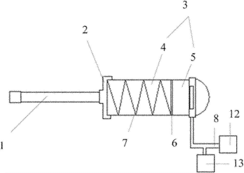
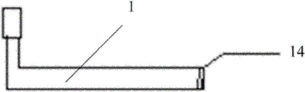
[0043] figure 1 It is a schematic structural diagram of the oil injection device provided in Embodiment 1 of the present invention, figure 2 It is a schematic diagram of the shape of the gun nozzle in the oil injection device provided by Embodiment 1 of the present invention. Embodiment 1 of the present invention provides an oil injection device, such as figure 1 As shown, it includes a gun nozzle 1, an end cover 2 and an oil cylinder 3, wherein a piston 6 is arranged in the oil cylinder 3, and the oil cylinder 3 is divided into two parts: a grease chamber 4 and a pressure chamber 5 by the piston 6; the pressure chamber 5 is provided with a liquid inlet , used to communicate with the pressure liquid power source 12 through the introduction pipeline 8, and push the piston 6 to move toward the grease chamber 4 by filling the pressure chamber 5 with pressure liquid; the grease chamber 4 is provided with a spring 7, and the first end of the spring 7 Butt against the end cover 2,...

Embodiment 2

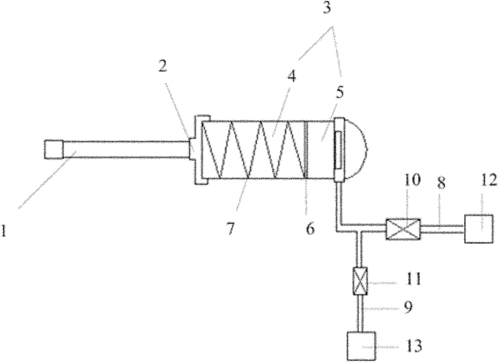
[0049] image 3 The structure diagram of the oil injection device provided by Embodiment 2 of the present invention. Embodiment 2 of the present invention provides an oil injection device. The difference from Embodiment 1 is that the pressure chamber 5 is further provided with a liquid outlet, and the liquid outlet is passed through the outlet pipeline. 9 is connected to the outside world 13, such as image 3 As shown, it is used to discharge the pressure liquid in the pressure chamber 5. The liquid inlet and the liquid outlet can be two independent openings, preferably as in this embodiment image 3 As shown, the liquid inlet and the liquid outlet are the same opening, and the inlet pipeline 8 and the outlet pipeline 9 communicate with the opening through a common pipeline.

[0050] Further, a pressure inlet valve 10 is provided in the introduction pipeline 8 connected to the liquid inlet to switch the conduction and disconnection of the introduction pipeline 8 when the pre...

Embodiment 3

[0054] Figure 4The flow chart of the oil injection method provided by the third embodiment of the present invention, the third embodiment of the present invention provides an oil injection method, using the oil injection device provided by any embodiment of the present invention, please refer to figure 1 and Figure 4 , the oil injection device includes a gun nozzle 1, an end cover 2, and an oil cylinder 3, wherein a piston 6 is arranged in the oil cylinder 3, and the oil cylinder 3 is divided into two parts: a grease chamber 4 and a pressure chamber 5 by the piston 6; the pressure chamber 5 is provided with a liquid The inlet is used to communicate with the pressure liquid power source 12 through the introduction pipeline 8, and to push the piston 6 to move toward the grease chamber 4 by filling the pressure chamber 5 with pressure liquid; the grease chamber 4 is provided with a spring 7, and the first spring 7 One end is against the end cover 2, and the second end is again...


PUM


Abstract

The invention provides an oil injector and an oil injection method. The oil injector comprises a nozzle, an end cover and an oil cylinder, wherein a piston is arranged in the oil cylinder, and moreover, the oil cylinder is divided into an oil chamber and a pressure chamber by the piston; the pressure chamber is provided with a liquid inlet which can communicate with a pressure liquid power source via a duct and pressure liquid can be filled into the pressure chamber via the liquid inlet to push the piston to move toward the oil chamber; a spring is arranged in the oil chamber, the first end of the spring abuts against the end cover, and the second end of the spring abuts against the piston. The oil injector provided by the invention utilizes the pressure liquid to push the piston to move to carry out oil injection, so that the speed of the oil injection is increased, and therefore the production efficiency is increased.

Description

technical field [0001] The invention relates to mechanical lubrication technology, in particular to an oil injection device and an oil injection method. Background technique [0002] Coal mining machine, fully mechanized mining machine necessary mechanical equipment for coal mine engineering, the walking transmission mechanism of the coal mining machine is mostly gear pin row type, the rack wheel and driving wheel assembly of the traction part, and the fully mechanized excavator rotary table bearing and cutting The internal bearings are subjected to heavy loads and low speeds. Once running without oil, it is easy to cause premature damage to the driving wheels and bearings, resulting in mechanical accidents. These devices often need to be injected with lubricating oil to work. [0003] To provide lubricating grease for the equipment, the oil injection device has become an indispensable tool and is widely used in coal mines. The existing oiling device generally includes a g...

Claims


Application Information

Patent Timeline
Patent Type & Authority Patents(China)
IPC IPC(8): F16N13/16F16N21/02F16N23/00
Inventor 杨同厂贾维志刘广玉张安苏磊
Owner HUAINAN MINING IND GRP
Why Eureka
Try Eureka